I know how busy Jack must be, but hopefully
One simple 2 part question
Box volume recommendations for the 8 and 6.5 speakers
and port tube diameter
Hopefully that did not hurt too much LOL
I am planning on building a M/W T - T M/W using 6.5s XT25TG30-04 and D26NC-55-06 😀 😀
Plus Jack is very patient and willing to work with us DIYers I just wish they had a FR chart and box volume, yes I know that would be asking too much with all the great things Jack has done.
I am anxiously waiting for the items that I ordered to start figuring out what my choices will be. 😀 😀 😀
😀 😀 😀 
One simple 2 part question
Box volume recommendations for the 8 and 6.5 speakers
and port tube diameter
Hopefully that did not hurt too much LOL
I am planning on building a M/W T - T M/W using 6.5s XT25TG30-04 and D26NC-55-06 😀 😀
Plus Jack is very patient and willing to work with us DIYers I just wish they had a FR chart and box volume, yes I know that would be asking too much with all the great things Jack has done.
I am anxiously waiting for the items that I ordered to start figuring out what my choices will be.
😀 😀 😀 Member
Joined 2003
Just thought I'd give an update to my progress. I've been very busy at work (haven't had a day off for two weekends now 🙁), so I have not had the time to try the resistor change in my crossover. I ordered the parts to adjust the notch filter anyway though, if it doesn't help, it surely won't hurt. It wasn't very expensive, just a cheap Jantzen 0.05mH 18AWG air core from Parts Express, and another 3.9uF for each speaker.DcibeL said:Hmm, that looks like a very small difference to have a significant effect on the sound. I have some 2 Ohm resistors in my stockpile of parts, so I may try that, it'll be fairly easy to do even with the mess of a crossover I built. Looks like it will make the response a bit flatter, lowering a bump at 4.3kHz
I may have changed my mind on this whole "just unwind the inductor a bit" idea. I think it may let more of the fundamental cone resonance through, which will likely only make things worse. I'd have to buy the extra caps, and unwind the inductor a fair bit to get real results, which I'm not sure I'd really want to do without being able to measure the resulting value of the inductor. Being off here could be detrimental, so I will try the resistor change first.
I really despise giving people the answer to questions like this, since they don't learn anything in the process. I'm a firm believer in giving someone a physics book at my expense rather than just handing them the answers even if it costs me nothing.
I would go here: http://www.diysubwoofers.org/ This wesbite has practically everything you need to design a subwoofer, in a very well organized fashion. Click on the links on the left side for the type of enclosure you want to build. Below this are links for calculating the enclosure volume, port tuning frequency, port dimensions, etc. I would spend a few hours and read as many pages on this site as possible.
The DIY site above is dedicated to subwoofer design, but that is really a misleading title. The website is really about the low frequency performance of any speaker system, subwoofer, woofer, midrange, TWEETER, etc. The exact same math and design process applies. It is just the particular frequencies involved that change.
If you get stuck or can't figure something out, then ask specific questions.
B-20 Control Amp
Jack,
Is it possible to post the Boundary EQ curves for the B-20 Control Amp? I would like to build a pair of subwoofers and tailor the box design around the existing EQ of the amp.
Also is the B-20 4ohm stable?
Thanks
Jack,
Is it possible to post the Boundary EQ curves for the B-20 Control Amp? I would like to build a pair of subwoofers and tailor the box design around the existing EQ of the amp.
Also is the B-20 4ohm stable?
Thanks
I'll have to look for the curves later.
The schematic is attached. The boundary eq and HP filter are on page 3 just before U7. It is a 3rd order HP with variable Q.
The B-20 woofer module was a 16" cube with 0.820" thick walls. You could put the driver in a larger box. This will allow it to play louder at low frequencies, since the amplifier will be able to get the driver closer to Xmax. You would need to modify the EQ curve to do this.
The B-20 is 4 ohm stable, but I wouldn't use it with a minimum impedance much below 4 ohms. The woofer in the B-20 is a 4 ohm driver, but the sealed box raises the average impedance quite a lot.
Attachments
Thanks for the schematic.... what is the power output of the b-20 amp into a 8ohm load? 250W per channel?
Jack,
If I were to have someone make some custom baffles for my 5.25" NPT-11-080-1's, would these mechanical dimensions be accurate?
http://www.tymphany.com/files/products/pdf/850108.pdf
Barry
If I were to have someone make some custom baffles for my 5.25" NPT-11-080-1's, would these mechanical dimensions be accurate?
http://www.tymphany.com/files/products/pdf/850108.pdf
Barry
Barry,
That frame is the correct one, so the baffle dimensions can be taken from that drawing. I just noticed that my spreadsheet had the wrong dimensions in it for this driver. I've fixed that.
The magnet depth and OD will be different. The 080 driver has a shielding can and bucking magnet. This will make it larger diameter and deeper. It will not affect the diameter of the thru hole in the baffle. If you need these exact dimensions, let me know.
Jack,
As usual another quick reply. Thanks much!
I am comfortable measuring driver depth for my boxes as I will be making them myself.
Getting accurate measurements off to someone who will cut baffles (using CNC router) is another story.
Thanks again,
Barry
As usual another quick reply. Thanks much!
I am comfortable measuring driver depth for my boxes as I will be making them myself.
Getting accurate measurements off to someone who will cut baffles (using CNC router) is another story.
Thanks again,
Barry
Member
Joined 2003
FYI, Zaph has posted his take on a crossover for the XdS speakers a couple days ago. He uses 0.08mH in the notch filter, and I'm not sure where he gets them from unless they're a fancy copper foil inductor from PE. Options for reduced BSC are there as well. My own design uses even less BSC, as I plan to use the speakers attached to wall-mounts so they will be rather close to a wall.
There is mention at the end of the page about mounting the W15 to a lathe and sanding the black off the phase plug to reveal the copper plug underneath, however I'm certain I read a post from Mr. Hidley that these W15 drivers have an aluminum plug.
My crossover design that I have been tweaking is finalized, I will post the details later today.
First post, many more to come. This one would be considered feedback, I'm sure the next will be in the question category. UPS just pulled out of my driveway after delivering my beautiful new drivers. I would like to thank Mr. Jack Hidley for providing me with the foundation of my new speaker system. Four boxes containing 16 carefully packaged drivers for my 3.3 and AC2 clone attempt. I hope I can contain my enthusiasm and patiently craft the cabinets and electronics to bring my vision to life. I do have one question, do I have to wait for the website to return to life or can I place an order for the subs based on the existing inventory sheet?
Thanks again to Jack!
Thanks again to Jack!
Member
Joined 2003
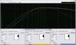
Here's my final crossover design:
IMAGE: Crossover Schematic
IMAGE: Final Crossover response, phase, transfer function, impedance
For comparison, using the same driver response, software, etc.
IMAGE: Jack's crossover supplied with the measurement package
IMAGE: Zaph's crossover with reduced BSC (series inductor with woofer = 1.7mH, parallel resistor with tweeter = 20 Ohms)
I compared Zaph's crossover with reduced BSC because it is the most comparable to my own design. Note that this is reduced BSC from the Zaph standard, it is in fact increased BSC from my design point.
Enjoy!
[Edit: Link correction]
HL2, I think you may have to wait for Jack to get the site back up and running again.
I do recall him saying that he would still be able to sell the AR-12 subs, the 15" Jensen subs, and the Foster amps. But the rest was going to have to wait until inventory was finalized.
BY THE WAY, I just got done building the VC-3 and VR-3 clones and they sound incredible.
Good luck on your build.
DcibeL said:Here's my final crossover design:
IMAGE: Crossover Schematic
IMAGE: Final Crossover response, phase, transfer function, impedance
For comparison, using the same driver response, software, etc.
IMAGE: Jack's crossover supplied with the measurement package
IMAGE: Zaph's crossover with reduced BSC (series inductor with woofer = 1.7mH, parallel resistor with tweeter = 20 Ohms)
I compared Zaph's crossover with reduced BSC because it is the most comparable to my own design. Note that this is reduced BSC from the Zaph standard, it is in fact increased BSC from my design point.
Enjoy!
[Edit: Link correction]
Did you get confirmation that it's actually a Seas 27TAF?
Member
Joined 2003
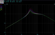
X1 EQ Curves
I have attached the stock X1 EQ curves if anyone is interested in seeing what they look like... and if they might be useful to one of your projects. The curves represent 20% turns of the EQ knob.
Jack,
If you had a chance to modify a X1/2 schematic to work with the XdW, I will update my simulation and post the results here.
Attachments
- Home
- Vendor's Bazaar
- For Sale: NHT Loudspeaker drivers and amps-Discussion Thread