Question about the heatsink. Do you need to secure it to the enclosure or is the single screw at the tda7297 enough to support it?
hi cspirou, I found this info in the audiocircle thread, see this post and the followup
Folsom's great little 7297 Chip Amp
summary: "If you're worried about the transistor and the rather light heatsink you can add a little solder to the legs of the transistor to coat them top to bottom. But the one I recommend doesn't seem to budge at all during shipping."
good info in that thread, but it's long and hard to search. make sure you don't have continuity between the uh.. screw, washer and heatsink? something and something I forget 😛
Last edited:
Question about the heatsink. Do you need to secure it to the enclosure or is the single screw at the tda7297 enough to support it?
I guess that depends on how much you move it? It should have the insulating washer and mica to stop continuity between the chip tab and heatsink.
Did you not have the BOM and everything that explained it all?
I have the BOM and your notes. There’s a lot about alignment but no mention of attaching the heatsink to the chassis. Normally i wouldn’t worry but it seems rather large. It’s okay though, I can see what it’s like after it’s mounted to the chip.
Well I suggest using common sense. It's all mechanical, and not electrical at that point - so long as you use the isolating parts. There are plenty of case builders on the forum that I am sure would be happy to give advice on how to construct something.
I have the BOM and your notes. There’s a lot about alignment but no mention of attaching the heatsink to the chassis. Normally i wouldn’t worry but it seems rather large. It’s okay though, I can see what it’s like after it’s mounted to the chip.
I drilled and tapped the HS to attach it to the bottom of the chassis with screws.
Folsom's great little 7297 Chip Amp
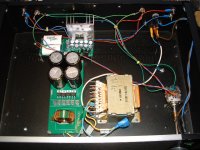
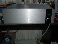
I finished this 2 hours ago I found it a easy build ,it worked without any problems (not all like that)
At max volume no sound coming from speakers I mean nothing I had to switch cd player on to satisfy myself it was on.🙂
The sound is top quality,, makes some of the highly regarded amps on here sound flat plus expensive to make !
I took your advise and got a stepped attenuator off ebay I am converted.
Thanks for giving us this what next you got to make
regards john
Attachments
I finished this 2 hours ago I found it a easy build ,it worked without any problems (not all like that)
At max volume no sound coming from speakers I mean nothing I had to switch cd player on to satisfy myself it was on.🙂
The sound is top quality,, makes some of the highly regarded amps on here sound flat plus expensive to make !
I took your advise and got a stepped attenuator off ebay I am converted.
Thanks for giving us this what next you got to make
regards john
Your input signal wires are running pretty close to the transformer. Could possibly pick up noise.
Hello, my headsink is hot on touch.. is it normal? Or i need a bigger one?
Tks
My heat sink is 3" x 1.5" and does not even get warm.
Paul
Is the chip heatsink....Chip heatsink? The D45 does get kinda hot when first in use for awhile but evens out a bit.
Hello, yes it has. it was my mistake, i put it on vertical and it does not dissipate well.Does it have any airflow?
I will put it horizontal in the right position.
I put it with the strips vertical way.. it is cold now 🙂
Could i ruin the chip by running hot for 2 weeks?
Could i ruin the chip by running hot for 2 weeks?
The heatsink get a bit hot after a few hours of playing...I doubt it.
But i think its normal..right?
Hello Jeremy,
can you explain a bit technically about rfi and emi interference on the board amp and trafo?
for example i have the trafo on a wood base without a metal case.
is the trafo getting interference from the outside or is the trafo emitting interference for the boards near??
and the other 2 boards? are they receiving external interference or themselves transmit interference or both??
regards
Nuno
The transformer, if you're using the Hammond 185, doesn't let as much noise through because it has higher loss in the RF range, so the lower voltage noise just doens't make it. So it can still get noise from the AC line going into it, but it transfers less than a toroid without a shield between the primary and secondary (and maybe still better than one with a shield, I don't know for sure).
The transformer doesn't emit RFI, but it does have a field that extends from it - which is comprised of 60hz. The field is there because it's what actually transfers power from one winding to the other, as the wires are not actually touching.
The boards themselves are going to get RFI from the air, since they are not in a metal, grounded, enclosure. But they are very specifically designed to reduce the amount that makes it to the signal. For example noise that does get in from the air or power is attenuated by the capacitors that are on a low inductance set of copper pours. As in they don't have traces, they have low inductance wide areas. Furthermore the section on the amplifier board that regulated voltage also rejects a lot of noise. Explaining that is a bit more complicated, but essentially to the circuit it looks like a big capacitor that doesn't like to feed noise through to the amplifier.
Neither board transmits much of anything. The amplifier board will have the largest fields from the speaker outputs if the wires are not twisted, because higher AC power will be going through them compared to the signal input which has small fields (real nice and small if they are twisted).
It's a good idea not to mix fields, which is why the layouts I've commended do a nice job of keeping wires separate, and keeping the transformers from being next to the amp board itself.
Last edited:
- Home
- Group Buys
- Folsom DIY7297 Amp & Antipole PSU