I have had some time to try a couple of things on this. First, I built a simple voltage source for the base of the cascode transistor made from a CCS feeding a bypassed resistor. I then added a ZTX558 follower to drive the cascode transistor base.
Unfortunately, neither circuit has improved on the noise performance of the measurements from post 28. Is this circuit just a lot noisier than the CCS-loaded pentode? I really expected some improvement on noise performance.
I guess I'll have a look at my negative rail next but I thought it was pretty clean...
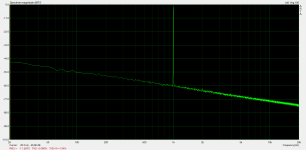
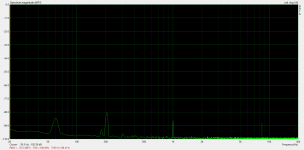
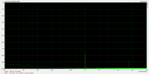
I just took a few measurements and attached here. All three are averaged spectrums during 22.5Vrms 1kHz test tone. Circuit output, negative rail, cascode base voltage, and GND.
Attachments

It certainly does not look like the supplies are creating the noise, since they only add noise to the output. Then again, the base noise is added to the output current, so if the load resistor is a very high value, that might be a driver for it.
The other noise source is the driver valve - the noise if of course stepped up by the voltage-gain factor.
The other noise source is the driver valve - the noise if of course stepped up by the voltage-gain factor.
@SpreadSpectrum how much noise do you get from it? I’m asking because with the configuration I want to try it (output tube in UNSET+UL), I need around between 250 and 300Vpp to drive it to full power, so the poweramp is not so sensitive to noise.
Have you tried the voltage regulator I wrote few posts ago?
Thanks!
Roberto
Have you tried the voltage regulator I wrote few posts ago?
Thanks!
Roberto
I was thinking along the same lines. I think I will set this aside for a bit and try to optimize the original 6BN11 input stage operating point in my amplifier and see what I can get out of that. Then I'll put the 6E5P in and see how performance changes in the overall amplifier.It certainly does not look like the supplies are creating the noise, since they only add noise to the output. Then again, the base noise is added to the output current, so if the load resistor is a very high value, that might be a driver for it.
The other noise source is the driver valve - the noise if of course stepped up by the voltage-gain factor.
Stay tuned. I don't work fast but I eventually get around to things.
I haven't measured the noise, but I may be able to do that with the meter in my Pete Millett soundcard interface. I don't remember the bandwidth of the RMS meter in there, but I think it was at least the full audio spectrum.@SpreadSpectrum how much noise do you get from it? I’m asking because with the configuration I want to try it (output tube in UNSET+UL), I need around between 250 and 300Vpp to drive it to full power, so the poweramp is not so sensitive to noise.
Have you tried the voltage regulator I wrote few posts ago?
Thanks!
Roberto
The noise is visible on the scope at 50V/div at a small fraction of one division.
I haven't tried the regulator. I'll have to include it in my next order. I've got four teenaged kids so I work pretty slowly and only get short periods of time to work on this stuff.

@SpreadSpectrum
have you done other tests on this circuit?
@Rod Coleman
is it possible to drive the shunt cascode through a pmosfet source follower at its cathode and apply feedback (local, at primary of the output transformer, global) through its grid, like in the schematic below (Q1 gate needs a low impedance supply, I know, that part is just a sketch)?
I remember you said you had a new version coming out, is it ready?

Thank you both,
Roberto
have you done other tests on this circuit?
@Rod Coleman
is it possible to drive the shunt cascode through a pmosfet source follower at its cathode and apply feedback (local, at primary of the output transformer, global) through its grid, like in the schematic below (Q1 gate needs a low impedance supply, I know, that part is just a sketch)?
I remember you said you had a new version coming out, is it ready?
Thank you both,
Roberto
No, I set this aside after more staring at the noise floor, particularly the LF side of the spectrum. I have no more updates since this thread, but I still have the breadboarded circuit and ten 6e5p. I'd love to play more with this one some day.
It is still an amazingly low distortion level for that much output and gain.
It is still an amazingly low distortion level for that much output and gain.
It can probably be made to work, but local (intra-stage) feedback is much better served with a cathode resistor. You can DC bias the grid +ve to allow a wide range of feedback/cathode resistor values. No bypass capacitor.is it possible to drive the shunt cascode through a pmosfet source follower at its cathode and apply feedback (local, at primary of the output transformer, global) through its grid, like in the schematic
Driving the triode's cathode with a FET source is more difficult, since you must correct for the phase in a closed loop (OTOH, no phase effects for any practical Rk value).
Also the open loop distortion is likely lower with the resistor. With a MOSFET, the source impedance varies with current, and it faces a cathode which also varies in effective resistance with current.
New version Shunt cascode is drawn out, with many attractive performance improvements. I am still stuck with ongoing distractions, but will do it soon, if slowly.
As for connecting a closed loop, maybe you can try to feed back to the cathode from some driving node. With positive grid bias, a resistor large enough to allow a divider may be an option.
Last edited:
It is indeed, and it has a very good harmonic pattern. Looking forward to see your updates, when you’ll have some.It is still an amazingly low distortion level for that much output and gain.
Thanks! Please keep us posted! What will be the benefits of the new version?New version Shunt cascode is drawn out, with many attractive performance improvements. I am still stuck with ongoing distractions, but will do it soon, if slowly.
- Home
- Amplifiers
- Tubes / Valves
- Folded/Shunt Cascode driver for 211