Group buy for the through-hole version has just been posted
https://www.diyaudio.com/community/...ugh-hole-folded-cascode-cen-iv-boards.391213/
Fran
https://www.diyaudio.com/community/...ugh-hole-folded-cascode-cen-iv-boards.391213/
Fran

For the 2sk170/2sj74 matched pair, aim for around 8mA or so at 7V (one pair per channel)
For the 2sk170 matched pair, BL range (one pair per channel) In my beta build they were ~10mA.
For the 2sk170 matched pair, BL range (one pair per channel) In my beta build they were ~10mA.
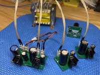
I’m part of the group buy for Patrick’s Cen iv (smd). Are these the power supplies you are using ?I felt a bit guilty as I was pretty slow at getting the beta build done - other things got in the way for a while. Over the last few evenings I built up a pair of these, verified basic functionality, and have them running now in the main system. They are sounding very good indeed - I don't think you would be sorry to have a pair of these at the end of your Miro DAC (or others) and it is certainly well worth the relatively low cost involved - a pair or valves could easily cost you more. The build is reasonably easy once you are comfortable with surface mount work (no really small stuff!). As usual, good soldering technique, patience and an organised workflow help a lot.
They are running now as I type this, using about 25mA per rail (15V rails) and while I have them running from a single supply, they really deserve their separate supplies. The sound is dynamic, very good transients/impacts, clean, very smooth, good deep and wide soundstage. I would say bass weight and impact deserves special mention - there is no lean sound here. I would consider this up there at the top of the pile in terms of the IV stages I've had.
There is still some testing on the cards which I hope to complete soon.
For reference:
Freshly serviced stacked Quad 57s
Solid state amplification
01a preamp based on Bartola valves recipe - gyrator anode supply, Coleman filament regs, source follower
Miro dac with SD card player source
Attachments
This one which is obsolete :
https://www.diyinhk.com/shop/eol-pr...-dac-power-supply-regulator-91215v-15ax2.html
now succeeded by this one :
https://www.diyinhk.com/shop/audio-...e-dac-power-supply-regulator-91215v-15a2.html
Patrick
https://www.diyinhk.com/shop/eol-pr...-dac-power-supply-regulator-91215v-15ax2.html
now succeeded by this one :
https://www.diyinhk.com/shop/audio-...e-dac-power-supply-regulator-91215v-15a2.html
Patrick
Yes, that is the one I used for initial testing.
Whatever one you use, if you have a scope it is very well worth while to check for oscillations. I have had it now a few times with different supplies on various other projects - and typically adjusting capacitor sizes or location of gate resistors are my first places to go to solve it.
For this build it is important that the supplies come up and down evenly. When you have that scope out, use it to capture the rise and fall with and even load before you connect it to the FC CEN IV.
We have had multiple questions as to whether the FC CEN can be used for DACs with an offset output current.
Examples are ES90xx, PCM179x, TDA154x, etc.
Such questions have already been raised before in the original SEN IV thread.
These modern DACs are designed to use single supply.
As such, they cannot output a +/- current, for which the FC CEN is designed.
So the offset current at no input signal has to be compensated for by an additional CCS.
The document for the Pedja Rogic IV shows how it may be implemented (Fig.1).
https://www.diyaudio.com/archive/bl...-out-production-pedja-rogic-ddnf-iv-stage.pdf
i.e. an adjustable CCS using a single JFET has to be placed at the DAC current output, and adjusted until IV output is zero with no signal.
What is not certain, is how stable that DC offset remains.
This in turns depends on the particular DAC, the stability of the JFET CCS, as well as the IV circuit itself.
Since it is impossible for us to test all the DACs that exists, all we can say is that the FC CEN is stable to << +/-5mV after 2 minutes.
Adding thermal mass with a special heatsink, as well as placing inside an enclosure, will improve that.
Another simple way out is of course to add an output coupling cap, as in the Rogic IV.
The through hole version will cope with a signal current of +/-4mA.
Beyond that, distortion will increase, unless you change the circuit for that ( with increased bias current and hence also DC drift).
And of course, Riv / Civ, and the Sallen Key filter have to be changed accordingly.
This is all we have to say on the subject.
Patrick
Hi Patrick. One quick question regarding the low pass formed with Civ (using THT version - no SK filter). Do you have a ballpark resistance value that I can use to calculate f3 for different value of Civ? Is it simply Riv?
What is not certain, is how stable that DC offset remains.
This in turns depends on the particular DAC, the stability of the JFET CCS, as well as the IV circuit itself.
Since it is impossible for us to test all the DACs that exists, all we can say is that the FC CEN is stable to << +/-5mV after 2 minutes.
So here you have it from Miro himself on the TDA1541.
https://www.diyaudio.com/community/...st-tht-i2s-input-nos-r-2r.354078/post-7159243
https://www.diyaudio.com/community/...st-tht-i2s-input-nos-r-2r.354078/post-7159250
I can only summarise what he said.
He prefers to use a (+ve) regulated supply and a resistor to null the ~2mA offset current, than to a current source.
(Rogic use a BF245A JFET adjustable CCS for the same purpose.)
There will be a DC drift from cold to warm, in the order of 7µA.
If you are using 1.4k Riv, expect 10mV change (on top of that of the FC CEN IV).
Of course you can trim it to close to zero after everything has warmed up.
I also agree with him that DC servo is not a preferred solution.
Resistor bias has poor PSRR, so you need a very quiet and stable supply.
And I have not tried, nor intend to.
Patrick
Hi Patrick,
The BC549/559 is essentially the same as BC550/560 but has a lower Vceo, I assume using 550/560 would be fine in this circuit, correct?
The BC549/559 is essentially the same as BC550/560 but has a lower Vceo, I assume using 550/560 would be fine in this circuit, correct?
The quad of matched JFET's in my stash has an Idss of 10.5mA which is a bit higher than recommended. Would there be additional adjustments needed if using these?
Thanks.
Thanks.
Thanks Jim,
I figured to post tech questions here and keep GB threads uncluttered.
Who knows though??🤪
I figured to post tech questions here and keep GB threads uncluttered.
Who knows though??🤪
Sorry to miss this. My apologies.
Hopefully not too late.
For use with AD1862, no need to change circuit even for Idss 10.5mA, though it is still advantageous to increase current in current mirror by 1~2mA.
If using a DAC with higher current amplitude (e.g. PCM63), you will want to increase the current in the current mirror by 2mA.
This can be done by changing R51,53,61,63 to 2.4k instead of 2k.
BC550/560 is perfect.
They are obsolete, which is why they were not named in the BoM.
Patrick
- Home
- Source & Line
- Digital Line Level
- Folded Cascode CEN IV with fixed Rails