I'm working on an FM tuner/MPX decoder design, and I'm trying to figure out how to design the audio output filters.
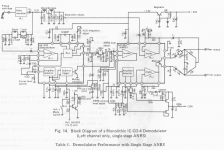
I found a schematic in the LA3410 MPX chip datasheet, but when I simulated it in PSpice, I found out it wasn't that good... Here's a frequency plot:
http://stiftsbogtrykkeriet.dk/~mcs/MPXFilter.gif
Not a lot of attenuation at 19kHz and -3dB somewhere around 13kHz.
The next thing I tried was "expanding" that filter with some extra sections. That produced this result:
http://stiftsbogtrykkeriet.dk/~mcs/F4V10.gif
Good attenuation of 19kHz and above junk, but some ripple in the audio band. Here's a close-up of the 1-50kHz range:
http://stiftsbogtrykkeriet.dk/~mcs/Not_nice.gif
To get a nicer looking curve I tried calculating a standard low-pass filter (6th order Linkwitz-Riley at 25kHz in this case), and then I added some caps accross the coils to create notches. This is the result I got from that:
http://stiftsbogtrykkeriet.dk/~mcs/Nice.gif
Looks very nice in the audio band, but the -3dB point has moved lower, and the 19kHz and above attenuation isn't as good.
So which filter would actually work best and sound best?
I have looked at some Toko datasheets for MPX filters also. They have about 25-30dB attenuation at 19kHz, and some of them higher at 38kHz. But I have no idea what circuit they use. Would they be better, or would a DIY filter with good quality parts (rather than ceramic chip caps) be a better idea?
If anybody has suggestions or experience in this field I would like to hear about it 🙂
Best regards,
Mikkel C. Simonsen
Hi,
here are filters I use on the tx side. The passive sounds better, IMO.
For more info check the old Revox and Studer tuners schematics.
http://www.prodigy-pro.com/forum/viewtopic.php?t=8107&start=15
Regards,
Milan
here are filters I use on the tx side. The passive sounds better, IMO.
For more info check the old Revox and Studer tuners schematics.
http://www.prodigy-pro.com/forum/viewtopic.php?t=8107&start=15
Regards,
Milan
Your schematic is exactly the same as mine 🙂
The values are very different though. How did you choose those exact values?
Best regards,
Mikkel C. Simonsen
The values are very different though. How did you choose those exact values?
Best regards,
Mikkel C. Simonsen
Isolate the pilot and mix it back into the audio out of phase, and null the pilot residual. Alignment would require phase and gain controls, but no filter, just pilot cancellation.
I often wondered about forgoing the deemphasis filter untill the 19KHz filter had been finalised it is quite probable a deep filter would do much of the deemphasis by itself. Also agree with above - pilot tone cancellation should always be first port of call. Thinking about it, a well designed LPF should deal with all admirably don't forget 38KHz switching artefacts also.....
The pilot is down 20dB from 100% modulation already, de-emphasis would take it down another 20+ dB, a bit of cancellation and you're done. Anything below 60dB would be into the noise floor. A high-quality multi-pole LPF should not be necessary, certainly not desirable either. 38kHz artifacts are all above 38kHz, starting at 3rd harmonic, so just not an issue.
I've never seen a LPF pilot filter in a receiver. Pilot cancellation, all the time.
I've never seen a LPF pilot filter in a receiver. Pilot cancellation, all the time.
Have a look at the CLCR filters used in the HH Scott 335 and 350 series for an all-in-one design. There are a couple of versions of kater one having a shunt C across the L as well. Requires pretty accurate 50mH inductors.
Wow, those are horrible. I just ran a simulation, yuck. And expensive to make. A 19kHz notch would have worked better. But it's all unnecessary, so thanks for the history, but I think we can move on.
Which just goes to show why everybody stopped doing all-in-one filters. It was all the rage for about five years. See also the McIntosh MR67 &ff.
De-emphasis should be done with a single pole filter wih the correct time constant, and the other stuff handled separately.
De-emphasis should be done with a single pole filter wih the correct time constant, and the other stuff handled separately.
- Home
- Source & Line
- Analog Line Level
- FM MPX filter
