Seems odd that we don't have a Tuner section here at DiyAudio.
I remember a new FM discriminator being talked about in the late 1970s that involved an
Xor gate to generate pulses on the zero crossings of the FM signal. Pretty sure this was
the Schotz demod but I seem to read more about Schotz "noise reduction".
It was used in Proton, NAD, and perhaps a few others and had an inherent advantage
over other discriminators.
Anyone have a link to a better description of this FM discriminator?
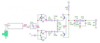
The so-called quadrature detector for FM consists of a delay circuit that produces a phase difference that depends on momentary frequency, and a phase detector. The phase detector is often a circuit similar to the Howard Jones circuit shown here: Gilbert cell - Wikipedia . In an FM detector, the input signals are made large enough to drive the differential pairs into clipping.
You can regard the Howard Jones circuit of which the inputs are driven into clipping as an EXOR gate made in current steering logic. An EXOR gate made in any other technology will work just as fine as the phase detector.
The delay circuit is typically an LC filter or an integrated low-pass filter, but in the Studer A726, it is a length of coaxial cable. That results in a very linear relation between momentary frequency and phase difference, and in a very heavy FM tuner.
I think it's very odd indeed. I see no reason to lump tuners, turntables, cartridges, various kinds of tape, &c. together under Analogue Source when they have so little in common. Also to distinguish SS from valve in power amps but not in preamps.
Having too many categories has downsides too. You could argue this subforum could be split into phono and the rest, based on the volume of threads, but you could also argue it could be split into mechanical v. electronic sub-forums.
Having a separate tape forum might be rather low-bandwidth and start to look deserted and inactive - I think its better each subforum is in fairly constant use and diverse so peoples' paths cross more - and variety inspires more projects and ideas I think.
How different is the FM discriminator referred in the OP to the Pulse-Averaging Discriminator described here?
An XOR with delay on one input is IIRC a pulse generator on zero crossing
and therefore it looks to be essentially the same as what is in the link. I
recall that it involved a delay element and an LPF at the output.
Software Defined Radio
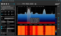
Lots of interesting stuff in radio signal processing these days. I have a book on 4GLTE that is written by 40 authors, most of which is over my head. I did work with various phase detectors including PLLs and DLLs for datacom purposes. FM radio today has become complicated by Hybrid Digital (HDFM) and Radio Data System (RDS) that embeds track tag data and album art along with the audio. In any case, it's all been integrated and it's fun to play with Software Defined Radio like the cheap Adafruit USB RDS receiver. It was intended for European digital TV DVB decoding but it works fine for Stereo FM in North America, and much more if you add an appropriate antenna. This is a capture of some local FM band. Note the HD sidebands and the RDS text. I suppose the point is that a computer has become the head end for most everything.
Lots of interesting stuff in radio signal processing these days. I have a book on 4GLTE that is written by 40 authors, most of which is over my head. I did work with various phase detectors including PLLs and DLLs for datacom purposes. FM radio today has become complicated by Hybrid Digital (HDFM) and Radio Data System (RDS) that embeds track tag data and album art along with the audio. In any case, it's all been integrated and it's fun to play with Software Defined Radio like the cheap Adafruit USB RDS receiver. It was intended for European digital TV DVB decoding but it works fine for Stereo FM in North America, and much more if you add an appropriate antenna. This is a capture of some local FM band. Note the HD sidebands and the RDS text. I suppose the point is that a computer has become the head end for most everything.
Attachments
This type of FM demodulator is perfectly linear, unlike the common tuned circuit solutions. I wonder what is the noise performance? Perhaps it needs another down conversion to 450 kHz to have acceptable S/N.
Depends again on how you make the delay. When it is made with some RC circuit that hasn't quite settled yet when the next transition comes, the linearity will not be perfect.
In the seventies I built my own fm tuner. The unique part was the if-amplifier consisting of 4 discrete amp stages each with a linear group delay 6-circuit LC-filter, delivered by Toko. This was the answer to the poor audio quality available with these common ceramic filters producing annoying audible distortion no matter how good you were in tune. The remaining components: A Görler dual-varicap tuner, CA3089-demodulator and MC1310 stereo decoder. Finally I added a squelch that triggered reliablely on side-band noise when detuned. That's a long time ago")
Last edited:
In the seventies I was working at Elektor and designed several FM receivers and some got published. Also, several IF strips were published plus stereo decoders. But living in the vicinity of borders with Belgium and Germany, plus the altitude of ~120m above sea level soon reminded of the issue that a well designed PLL would result in better reception (lower threshold, better co-channel suppression). The best of both is a PLL where the VCO is used with a low-distortion pulse demodulator.
A pulse count detector is the most linear of the FM discriminators but it has its own set of problems as can be seen on Kenwood, Akai, Nikko, Crown and Sansui tuners that used them. The detector will put out unwanted signal when tuning between stations. The problem is more evident on analog tuning where you have infinite tuning step.
Pulse count detectors need a very strong signal to work.
A ratio-detector can be made linear and produce THD < 0.005% at 75kHz deviation. I have state-of-art setup so I can routinely make these kind of measurements with FM stereo tuners.
PLL detectors with distortion cancellation works on paper. They deteriorate pretty quick in a a matter of seconds.
The Accuphase T-106 used the XOR method with a delay line. Their brochure clearly shows this. Haven’t tried it so no clue how good it is.
Last edited:
- Status
- This old topic is closed. If you want to reopen this topic, contact a moderator using the "Report Post" button.
- Home
- Source & Line
- Analogue Source
- FM Discriminator With XOR Gate