Hi modder,
The decoder chip would not be at fault unless the mono signal was off as well. It wouold be more liely to be external parts or adjustment.
Do you have a stereo signal generator?
I made one of these demodulator boards in the 70's. I can barely remember setting it up now. It did work fine though, for years.
-Chris
good bit of info
I don't have a stereo signal generator - could it be derived somehow with proximity to another FM tuner ? I have a portable SANGEAN radio.
Good bit of info re the mono signal - if that is working the decoder is OK. I will look at stuff around the decoder chip. The decoder chip puts out a left and right channel wit the right channel voltage being lower.
How does FM alignment work ? Once the FM range is found and stations can be pulled in then both left and right channels will decode at equal volume ?
Hi modder,
I'm going to have to look that chip and application info up. It's been too long to trust my memory.
Anyone else familiar with this chip is free to hop on in here!
-Chris
Edit: I downloaded the data sheets for these chips. I have never had this fault so I'm at a loss to explain it. The CA3090 gets tuned to 76 KHz with one inductor. That's all teh tuning there is. You need a frequency counter and adjust the free run freq. to 76 KHz. The 3089 has an adjustment for the IF frequency (10.7 MHz) and a muting level control. It's possible if some adjustments are way out to have odd things happen.
Decoder problem??
Hi` Modder
If You have any problems with your stereodecoder, I can probably help you, can you send me the schematic you are using and some detailed info.?? I have seen this problem before and solved easily, by some simple component changes.. Check your input network to the decoder, not to introduce any phase shift. This could cause your problem..... Drop me a mail If you need a diagram...
The IF stage is not your problem, but here I can help you too....If you need help.
Regards
Tamas
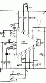
schematic attached
Schematic attached for decoder.
R226 and R227 do not go to 13v. They go from L/R to pin 11 of IC 202, the CA 3090AQ.
C227 is a 22 uF tantalum
R217 is 50K (and not 10K)
NTE equivalents of these ICs are NTE 788 and 789.
Thanks for all the help - amazing to know I am not alone in this FM world!
Unfortunately the attached GIF is too big and will not load even though it's only 92K.
Too many pixels.
Hi Modder
If you send it to me, I'll try and massage it to fit.
rpappsATtpgDOTcomDOTau
Cheers
Rob
If you send it to me, I'll try and massage it to fit.
rpappsATtpgDOTcomDOTau
Cheers
Rob
Decoder problem
Hi´Modder
Pls. send me your postal adress by email, and I send you a new Chip you can add to your tuner, a superb one 🙂, with the necessary diagram, the one you are using, the CA 3090, is a old RCA version, not the best 🙁,
If you want to use the old RCA type, then check the values of c213,c214,c216, if these values vary just a few percent, you will get a phase error, resulting in bad stereo, you can also try to add a trimming capacitor in parallel with R221, (philips green type 2-22pF), and then adjust slightly to get best channel separation.
In one of my earlier designs (For NAD S-400) this was added, and this improved channel separation.
Before change: L>R = 25 dB R>L = 42 dB
After change and adjust: L>R = 54 dB R>L = 56 dB
See example on att. file. for NAD S400
Attachments
I did a search on the TDA1592 thinking it would take me to the Phillips website, but ended up at http://www.shanling.com/product_e.html . Take a look at the TU 100 FM tuner. This company makes beautiful equipment.
Regards,
Ray
Regards,
Ray
Hi Andrew,
I thought I saw the information somewhere. Silly me! 🙄 I thought it would be in the data sheet.
Please accept my apologies. As a high voltage device, I do not expect they would be as fast as the equivalent lower voltage device.
-Chris
I thought I saw the information somewhere. Silly me! 🙄 I thought it would be in the data sheet.
Please accept my apologies. As a high voltage device, I do not expect they would be as fast as the equivalent lower voltage device.
-Chris
alignment
Thanks for the alignment tips anatech - I will have another go using your info.
rpapps in Sydney - it's a long way to post an embarassingly bad bit of soldering so I will hang on to it a little while longer and try to fix it here (but not using No8 wire).
Thanks for the alignment tips anatech - I will have another go using your info.
rpapps in Sydney - it's a long way to post an embarassingly bad bit of soldering so I will hang on to it a little while longer and try to fix it here (but not using No8 wire).
Hi Modder
Sorry, I should have expressed myself more clearly.
What I meant was send me the schematic picture and I will attempt to shrink it to fit on the forum.
The offer still stands if needed.
Cheers
Rob
Sorry, I should have expressed myself more clearly.
What I meant was send me the schematic picture and I will attempt to shrink it to fit on the forum.
The offer still stands if needed.
Cheers
Rob
A more complete KA2265 dasheet :
http://www.datasheet.in/datasheet-html/K/A/2/KA2265_Samsungsemiconductor.pdf.html
I am interested by this stereo decoder, I thought there was nothing new available on the diy market since years.
http://www.datasheet.in/datasheet-html/K/A/2/KA2265_Samsungsemiconductor.pdf.html
I am interested by this stereo decoder, I thought there was nothing new available on the diy market since years.
Linsley-Hood Stereo Decoder
As a new kid on the lock, I am not sure wether this should be a new thread or not. Anyway, here goes:
Does anyone have the original John Linsley Hood 1987, 88 or 1990 ETI stereo decoder articles or the circuit diagram?
- I lost mine in house moves over the years.
Also, I seem to be blocked from emailing other mambers. Therefore can anyone suggest why this is?
Maybe Tamas Kiraly can help me with some advice as to a possible match for the output of a Leak Troughline valve tuner?
Martin
Linsley-Hood tuner
Hi Urbanebassman1,
I can help you with some schematics. Just email me.
---to a possible match for the output of a Leak Troughline valve tuner?---
Do you mean a stereo decoder ?
Hi Urbanebassman1,
I can help you with some schematics. Just email me.
---to a possible match for the output of a Leak Troughline valve tuner?---
Do you mean a stereo decoder ?
I am interested by this stereo decoder, I thought there was nothing new available on the diy market since years.
Hellow Forr and all
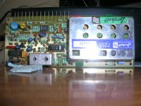
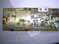
Tamas (Kiralyfalvy) did produce a kit with the KA2265. This was the kit LH7255. He was able to ship me the last completed kit he had.
Attachments
- Status
- Not open for further replies.
- Home
- Source & Line
- Analogue Source
- FM/AM Tuner


