In case you didn't notice, the RC is a high pass filter, and its purpose is to eliminate the DC component to allow LTspice to compute the rms value of the ripple only.In your spice sim, you added a CR circuit on the end. The reactance of 470 nF at 100 Hz is 3388 ohms. As you put a 470 kohm resistor in series, that will give substantial extra attentuation.
You can check that it works as advertised, the green and blue traces are identical, except for the DC level
.You don't need SPICE to work out circuits this simple. It's a quick bit of mental arithmetic,
In conclusion, something's wrong with Steve's measurement
Well well, than Steven is wrong, LTspice is wrong and I am wrong, as is the rest of the world, except of course your mental arithmetics....
That is something you should ask yourself.... too much red meat perhaps?What are you playing at Elvee?
PSUD2 is a very widely used and robust simulation tool for power supply performance assessment - even simpler than back of postage stamp calcs, and simpler for me than resurrecting LTSpice.
With the identified component values and 20Vrms transformer, the sim shows 16VDC for both configurations. The 33R configuration shows 850mVpp ripple, whereas the 33R+1.4H configuration shows 34mVpp ripple. That's a 25:1 ratio of pp ripple improvement. Surprisingly they represent the same nominal rms results Elvee and steven presented - shock horror.
With the identified component values and 20Vrms transformer, the sim shows 16VDC for both configurations. The 33R configuration shows 850mVpp ripple, whereas the 33R+1.4H configuration shows 34mVpp ripple. That's a 25:1 ratio of pp ripple improvement. Surprisingly they represent the same nominal rms results Elvee and steven presented - shock horror.
In case you didn't notice, the RC is a high pass filter, and its purpose is to eliminate the DC component to allow LTspice to compute the rms value of the ripple only.
.
Well well, than Steven is wrong, LTspice is wrong and I am wrong, as is the rest of the world, except of course your mental arithmetics....
QUOTE]
The circuit appears to show an output taken across the 470 nF capacitor.
It's not the tool that is at fault - its the person using it.
PSUD2 is a very widely used and robust simulation tool for power supply performance assessment - even simpler than back of postage stamp calcs, and simpler for me than resurrecting LTSpice.
With the identified component values and 20Vrms transformer, the sim shows 16VDC for both configurations. The 33R configuration shows 850mVpp ripple, whereas the 33R+1.4H configuration shows 34mVpp ripple. That's a 25:1 ratio of pp ripple improvement. Surprisingly they represent the same nominal rms results Elvee and steven presented - shock horror.
850 mV Pk-Pk is in reasonable agreement with my approximate 1 V. But Steve said he measured 0.15V. Assuming he had indeed measured RMS, that's 0.44V Pk-Pk. Not 0.85 V Pk-Pk.
Shock horror - there's still a discrepancy. Not between my calcs and your software - with with both of us cf Steve's data. Looks like my back of the envelope calc, which took perhaps one second to do, much faster than firing up computer software of any sort, got the answer needed. Its not compeltely accurate, but it didn't need to be.
Reality diverges from the model - so the natural conclusion is that reality is wrong🙄
Here's the simple question which should put this pointless discussion to bed, do you agree that a fluro ballast can offer about 20x the filtering of a equivalent DCR resistor ? If the answer is yes then that sounds like a recommendation to use one to me.
Br Cornelius
Last edited:
We don't need to look very hard to find faults in Keit's "mental" arithmetic.
We can see that he has taken ratios of impedance of capacitor, inductor and resistor, and treated them as if they were all Real numbers.
Electrical Engineers will know very well that reactive impedances must be treated as complex numbers, in order to take account of the (non-zero) phase-angle in complex impedances.
If you use Keit's method, any resemblance to the correct answer is purely random luck.
The circuit appears to show an output taken across the 470 nF capacitor..
If you say so, it must be right.... you are the expert after all
We don't need to look very hard to find faults in Keit's "mental" arithmetic.
We can see that he has taken ratios of impedance of capacitor, inductor and resistor, and treated them as if they were all Real numbers.
Electrical Engineers will know very well that reactive impedances must be treated as complex numbers, in order to take account of the (non-zero) phase-angle in complex impedances.
If you use Keit's method, any resemblance to the correct answer is purely random luck.
Real engineers know when to use precision, and when approximations will do perfectly fine.
Yes, normally you do use the complex number approach in dealing with reactive circuits. But here, as I have explained, the load resistance is so high compared with the reactance of the 470 uF capacitor, youy can just ignore it. It is a resistance of 82 ohm in parallel with a reactive 3.4 ohm.
Ok, let's do this with complex numbers:-
The parallel equivalent of 82.00 ohm resistive in parallel with -j3.400 ohm is the same as 0.1407-j3.3942 ohms. So the output ripple is:-
input Ripple x (82//-j3.4)/(series ressitance) = 10 x (0.1407-j3.3942)/33
which is equal to 0.0426-j1.0286 volts. This is an absolute voltage of 1.0294 volts.
Gee, I got 1 volt before, not 1.03 volt by doing it "properly" with complex numbers. Gee, how disgusting of me! 3% error! Shock! Horror!
Recall from my first post on the problems with Steve's data. While the math above shows we shouldn't trust it -he's made a measurement error somewhere - we can perhaps still get a sense of how well the choke is working.
Steve said the output ripple dropped from 0.15 V to 0.01 V. We can use this in a simple proportion test - no need for SPICE or fancy computer software. Because the load is insignifant at the ripple frequency, the choke reactance must scale by the same factor up from the series resistance:-
The choke impedance must be 33 x 0.15/0.01 = 495 ohms.
Strictly speaking its actually got the 33 ohm in series, so the reactance is a tiny bit less than 495 ohms: 494 ohms in fact (ie the choke impedance is 33+j494 ohms). But 495 ohms is close enough.
495 ohms inductive reactance at 100 Hz is an inductance of :-
495 / (2pi.100) ie 0.79 henries.
That's quite a bit below what even the heaviest fluoro choke would be under AC conditions (should be at least 1.5 to 2 henry) - it supports what I said in my first post - the flouro choke ought to work better than some people expect knowing that its an AC choke not designed for carrying DC, because in fact it does actually have a magnetic gap. But it won't work as well as you would expect if you assume its inductance dosn't drop with the DC load.
I didn't introduce the issue of the choke dropping in inductance due to being designed for AC only, someone else did. I merely pointed out it will actually work better than they expect, albeit nowhere as good as a purpose designed choke. Nothing has shown me wrong.
All this is most likely easily resolved if Steve comes back and tells what he measured across the first cap, and what he used to measure it with. And confirms he tested with full wave rectification ie 100 Hz ripple. We've all just assumed that.
Last edited:
This is a straw man argument !That's quite a bit below what even the heavist fluoro choke would be under AC conditions - it supports what I said in my first post - the flouro choke pought to work better than some people expect knowning that its an AC choke not designed for carrying DC, becaue in fact it does actully have a magnetic gap. But it won't work as well as you would expect if you assume its inductance dosn't drop with teh DC load.
No one, and I mean no one, has made such a claim as that highlighted in your comment. Everyone knows that inductance will drop to a limited extent under load (this is a property of all inductors after all) but that was never denied by anyone. The point is that people have said repeatedly that within their limits they make effective DC chokes, to an order of magnitude better than a resistor. what also has to be remembered here is that their use has been advocated in light current applications such as preamps so the examples quoted represent the absolutely worst case scenario for their application - yet they still deliver.
You have made a straw man and are now proceeding to argue against it. Not clever or impressive behaviour.
Shoog
Last edited:
This is a straw man argument !
No one, and I mean no one, has made such a claim as that highlighted in your comment. Shoog
The claim was made by DF96 in his Post 4 in the thread linked by Elvee in his Post 2 of this thread. And the same claim was made by others in Elvee's linked thread and other threads in the forum. Go look.
Futher, in this thread Elvee claimed in his Post 23 that inductance will not change much until saturation is reached - his several posts in this thread shows he clearly thinks little change in inductance occurs until saturation occurs and that will be at above the peak current that any choke is designed to see in AC service - something that is true only in square curve ferrites. I'm glad you think he's wrong - you said "Everyone knows....".
What's not clever is people not checking their facts before attacking others, as in your comment above.
DF96's claim about inductance drop in fluoro chokes as they were not designed for power supply service is reasonable on the face of it. And his post was almost at the top of that thread and thus immediately visible on one mouse click in this thread - which is why I looked a bit deeper to correct a misconception that his well meaning post might have caused.
Last edited:
Retried test with more tube related component values.
CRC 180uF , 33R, 180 uF. AC in 84 V. Load 1 K Vout 100V. Ripple C1 0,97 VAC C2 0,27 VAC.
CLC , the same, with ballast instead of 33R. C1 1,11 VAC C2 18...22 mVAC.
Voltages measured with Fluke 83.
Clearly the ballasts are useful for moderate powersupplies like SE KT88 or something similar.
CRC 180uF , 33R, 180 uF. AC in 84 V. Load 1 K Vout 100V. Ripple C1 0,97 VAC C2 0,27 VAC.
CLC , the same, with ballast instead of 33R. C1 1,11 VAC C2 18...22 mVAC.
Voltages measured with Fluke 83.
Clearly the ballasts are useful for moderate powersupplies like SE KT88 or something similar.
The claim was made by DF96 in his Post 4 in the thread linked by Elvee in his Post 2 of this thread. And the same claim was made by others in Elvee's linked thread and other threads in the forum. Go look.
What's not clever is people not checking their facts before attacking others.
DF96's claim about inductance drop in fluoro chokes as they were not designed for power supply service is reasonable on the face of it. And his post was almost at the top of that thread and thus immediately visible on one mouse click in this thread - which is why I looked a bit deeper to correct a misconception that his well meaning post might have caused.
If you read through those threads you will have to acknowledge that their general conclusion was that fluro ballasts make generally useful chokes despite the fact that their inductance tends to fall under increasing load. This is the claim that has been made in this thread, and the one which is actually useful to the person who actually asked the question.
You are been unproductively augmentative as others have pointed out.
Shoog
despite the fact that their inductance tends to fall under increasing load.
Shoog
That is actually the general case for common inductors as well....the amount depends from case to case (quality, design, size etc...)
Retried test with more tube related component values.
CRC 180uF , 33R, 180 uF. AC in 84 V. Load 1 K Vout 100V. Ripple C1 0,97 VAC C2 0,27 VAC.
CLC , the same, with ballast instead of 33R. C1 1,11 VAC C2 18...22 mVAC.
Voltages measured with Fluke 83.
Clearly the ballasts are useful for moderate powersupplies like SE KT88 or something similar.
Well, that is a completely different set of circumstances to your first test - so we still can't determine what went wrong in that first test.
On a quick back-of-the-envelope estimate, your voltages this time are reasonable taking into account tolerances on the capacitors. But your load current is now only 100 mA (in your first test it was nearly double that) so the choke is not tested anywhere near as hard and should perform better.
You are correct it will be fine for an SE output. But as SE must be class A, regulation is a non-issue, so a resistor can do the job more conveniently and look more authentic. The energy loss in the resistor, necessarily higher than 33 ohm for the same ripple of course, is not a concern. If saving energy and saving the planet was your concern, you wouldn't be building Class A tube amps.
Last edited:
A somewhat disingenuous quote when the same DF96 freely admits that he doesn't know about the construction of ballasts two posts later. He probably thought they were made of a homogeneous magnetic circuit, without gaps or easily saturable sections.The claim was made by DF96 in his Post 4 in the thread linked by Elvee in his Post 2 of this thread. And the same claim was made by others in Elvee's linked thread and other threads in the forum. Go look.
He is still present on the forum, and he may comment, I do not want to put in his mouth words he didn't mean to say
I maintain what I said, and here again is an example of disingenuous quote.Futher, in this thread Elvee claimed in his Post 23 that inductance will not change much until saturation is reached - his several posts in this thread shows he clearly thinks little change in inductance occurs until saturation occurs and that will be at above the peak current that any choke is designed to see in AC service - something that is true only in square curve ferrites.
I said this:
More generally, the permeability and inductance fall sharply when the instantaneous current pushes the induction into saturation
but this was an answer to this:
So, are we agreeing? In fact, permeability and inductance do fall sharply when some arbitrary threshold is crossed, but the result is only obvious from the outside when the magnetic circuit is perfectly closed: when an air-gap or something equivalent (thinner sections) is present, the inductance (the black-box parameter) falls off in a more gradual way.It is well known that inductance falls sharply with the amount of DC current carried. The airgap reduces the fall off. The fact that inductance falls off sharply in iron cored chokes is the basis of magnetic amplifiers - I suggest you look these up too.
Enough sterile nit-picking, let us go back to the core issue: I said (and I have to quote, due to hostile environment):
So, let us examine the behavior of such a ballast near its nominal peak current.This is a false problem: these are "reactors", not transformer's primaries, and they are designed to withstand the peak value of their normal operating current without saturating significantly.
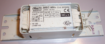
The example I chose (because I had it handy) is a 38W nominal model made by ERC.
Its characteristics are:
DC resistance (cold, 20°C): 42.8Ω
Initial inductance (100Hz, small signal, zero bias): 1.06H
Parallel equivalent capacitance: 158pF
I have measured the inductance for various bias currents. The measurement is true incremental (100Hz), and the DC bias is never reversed and always increasing, to mimic the actual operating conditions of a DC choke, in case it is questionned.
Code:
Current    Inductance
 50mA        1.07H
100mA        1.05H
200mA        1.01H
300mA        0.955H
400mA        0.880H
500mA        0.801H
600mA        0.700H
There is first a small increase in the inductance (not unexpected), then a steady decrease with increasing current.
At the peak operating current the reduction is a little more than 30%. But of course, you are not allowed to operate this choke permanently at such a current (~0.6A): the maximum rms value is 0.43A, and that should also be the maximum DC current, preferably a little less to run cool.
At 400mA, the inductance reduction is ~17%.
Thus, the statement
seems to hold.and they are designed to withstand the peak value of their normal operating current without saturating significantly
Does it really come as a surprise?
Attachments
I'm going to pick up a few EC9 at AUD$6 each to give me some more options in future valve amp renovations. For restoring old PA amps to a guitar future, the introduction of a CL pre-filter has many advantages, not the least is a big drop in audible ripple whilst still keeping a 'minimal' capacitance path for B+ and screen. The other main advantage for me is to allow cheaper 6L6GC variants to be used instead of needing EL34s if the original B+ was getting up.
I was happy to use EC18/20's because I have a freeby box of them.
I was happy to use EC18/20's because I have a freeby box of them.
MEC86 has R about 30-40 ohm and it is working with currents about 40-50 ma.
For ex.....if You use ECL82-86 You can use after rec. tube CLC /33uF-MEC86-470 uF/.
For ex.....if You use ECL82-86 You can use after rec. tube CLC /33uF-MEC86-470 uF/.
It's not the tool that is at fault - its the person using it.
Unless of course it is a Fluke 45 dual display multimeter purchased about 25 years ago!! hahaha😛
Unless of course it is a Fluke 45 dual display multimeter purchased about 25 years ago!! hahaha😛
Nah...
Fluke recalled them 25 years ago, shortly after I bought mine, and the local Fuke dealer updated the software, and returned it to me. Its' had it's yearly calibration check each year since, as is required by my customer's quality management,and all is well. 😛 Actually, I have 2 more of them to meet lab requirements.
- Home
- Amplifiers
- Tubes / Valves
- Fluro Ballast as DIY choke?