Anyhow, you can always design yourself a log spaced line and mount it horizontally on the wall. It should satisfy all your wants.
David - I don't see it that way. 🙂 I see all kinds of problems and limitations. But then I am not limited to the choice of a few drivers. Given that limitation I might go with a line array. But not starting from a clean slate.
Hi Patrick,
Actually this will have 9 full range units of small size, so not a big speaker like the Snell XA. Not really going for state of the art but more seeing how to achieve more uniform directivity and polars with no side lobes.
We are using a lot of DSP and modest power chips on each element in our systems here. What's especially cool is arrays that radiate with 3 independent axis. (left center and right with L and R bouncing off the side walls) So that is a combination of end fire and broadside radiation in one cabinet via shared drivers. Most of the systems use a limited number of drivers with fairly uniform spacing so the side lobes can be higher than you want (and when you consider a side radiating axis, then the lobes will cross the couch position, not good).
Regards,
David
Yes.
It's basic geometry:
If you have two sources playing 17,000hz, as soon as the pathlength difference between those two sources is more than half a centimeter they're going to interfere destructively.
With a line array, that's basically every position in the room.
This is why we have curved arrays and why we have shaded arrays. You can't change the fact that the two sources will interfere, but you can reduce the effect of that interference by moving and/or reducing the level of the other source. Amplitude shading and curvature does that.
That interference would be a big issue if there was only 2 drivers, much like being in an anechoic chamber with a single hard reflection. With a floor to ceiling line array using 3 inch drivers, for example, every null gets filled in by the rest of the drivers that will have their nulls at differing frequencies, for each point in the space of the room, so once you're a few feet out from the line array the nulls are pretty much inaudible.
Any vertical array of drivers putting out the same frequencies will be more directional on the Y axis, thereby reducing the effects of floor and ceiling bounce, which can be one of the bigger problems with a typical listening room. When a vertical line array goes all the way to the floor and ceiling, it's going to have a significantly different acoustic interaction with the room, than those short, curved, tapered arrays. Any speaker system has tradeoffs. It's arguable that the best speaker is the one that works best with room acoustics.
Shading is no good since small drivers have limited Xmax, so all drivers need to be fully operational in order to get adequate low end response. Using bigger drivers makes nulls more audible.
On the issue of sound images being too big with floor to ceiling line arrays, it's not the speaker that's at fault, but the recording process. If you jam a mic into the singers mouth, what would you expect? What would it sound like if you put your ear right up to a singers mouth? Too big? Compare this with a stereo head mic system several feet out from the singer. The best reason to go with a point source speaker is to undo this damage created in the recording process. The damage created by typical room acoustics can be worse than a singers voice being too large IMO.
Last edited:
Hi Patrick,
Actually this will have 9 full range units of small size, so not a big speaker like the Snell XA. Not really going for state of the art but more seeing how to achieve more uniform directivity and polars with no side lobes.
We are using a lot of DSP and modest power chips on each element in our systems here. What's especially cool is arrays that radiate with 3 independent axis. (left center and right with L and R bouncing off the side walls) So that is a combination of end fire and broadside radiation in one cabinet via shared drivers. Most of the systems use a limited number of drivers with fairly uniform spacing so the side lobes can be higher than you want (and when you consider a side radiating axis, then the lobes will cross the couch position, not good).
Regards,
David
Absolutely. As I understand it, an eXpanding array can use expensive drivers or small cheap drivers. the directivity is a result of the driver spacing, crossover frequencies, and slope.
DSP and digital amps makes this easier and cheaper. In the 90s doing this passively was an expensive proposition, because it requires a lot of frequency bands. In 2014 we can do it cheaper and easier.
Here's Speaker Dave's paper on loudspeaker arrays: http://www.classicspeakerpages.net/...e&module=attach§ion=attach&attach_id=5570
when you consider a side radiating axis, then the lobes will cross the couch position, not good).
Regards,
David
Glad you pointed that out because I could not see why you cared about side lobes - context is everything.
this assumes the speakers are aimed ahead and not "toed" in to cross at said couch?
I was giving an example of a TV sound bar type array that radiated in three directions at once. For the end fire left and right channel beams we want all energy to bounce off the side walls with minimal leakage in the forward direction. With leakage, precedence will take over and pull the image away from its intended location. (A sidewall bounce path will always be longer than the direct arriving leakage path.)
David
Shading is no good since small drivers have limited Xmax, so all drivers need to be fully operational in order to get adequate low end response. Using bigger drivers makes nulls more audible.
Not always the case. Frequently the goal is to make the effective line length proportionate to radiated wavelength. "Short at high frequencies and long at low frequencies" allows for arrays with units that are progressively low pass filtered in proportion to distance away from the array center. All units can be active at low frequencies, preserving LF power handling.
David
A picture is worth a thousand words, so I made one.
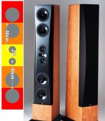
This is David's Snell XA Reference. As noted earlier in the thread, the crossover points dictate the geometry. According to David, "I tried a number of alternative schemes, but none of these alternative systems looked promising, so a more conventional symmetric array was settled on... The simulations showed that constant directivity came from having a constant element spacing relative to the crossover frequency. That is, if the highest crossover frequency is six times the next crossover frequency, the mid-to-tweeter spacing should be one sixth the woofer-to-tweeter spacing. Both of these spacings should be one third (at most, one half) the crossover wavelength. In practice, this means the mids had to be placed very close physically to the tweeter, and the top crossover point should be as low as practical."
In the illustration, we see that the Snell meets this criteria. The distance from the center of the midrange to the center of the woofer is 40cm. 850hz is 40cm long. Divide that by three and you get 283hz. Not coincidentally, the crossover from midrange to woofer is about 283hz. 300hz, to be exact.
The distance from the center of the tweeter to the center of the midrange is 8cm. 4250hz is 8cm long. Divide that by two and you get 2125hz. Not coincidentally, the crossover from tweeter to midrange is about 2.1khz. 2.4khz, to be exact.

Here's the frequency response.
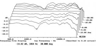
Here's the vertical polars. There's a bit of narrowing at the xover between the midrange and the tweeter (2.4khz) but otherwise the array is doing exactly what it's supposed to do. The narrowing above 13.5khz is due to the sound wavelength becoming smaller than the diaphragm.
If you stare at it for a bit, you'll realize a few things:
1) This concept applies to an array of any size. The Snell array is about a meter and a half from end-to-end, but there's nothing stopping you from extending the concept to two meters, or even three meters.
2) If you want horizontal directivity instead of vertical directivity, flip the array on it's side
3) If you like the sound of the Quad ESL, you could do this array in two dimensions and create something similar
4) Though Snell used drivers of dissimilar size, there's nothing stopping you from doing this design with a pile of full range drivers. For instance, if you used an array of nine 3" drivers you would have an array with a surface area that's like a 9" woofer, but with high frequency extension of a 3" driver. Not a bad combo, no?
Last edited:
Hopefully the phase shift introduced by the varying lo-pass filters wouldn't cause some other problem. It may affect directivity on the Y axis. If so, the goal of reducing floor and ceiling bounce may be compromised (?).Not always the case. Frequently the goal is to make the effective line length proportionate to radiated wavelength. "Short at high frequencies and long at low frequencies" allows for arrays with units that are progressively low pass filtered in proportion to distance away from the array center. All units can be active at low frequencies, preserving LF power handling.
David
Geee ..a rehash of the Dunlavy style speakers.
Which did work seemingly well, in the shop 🙂.
Enough to drag home a pair.
But were notably Less able..in real life.. than my ancient Tannoys dc's when directly A/B'd.
Why do so many try to reinvent the wheel.. with sketchy success?
Which did work seemingly well, in the shop 🙂.
Enough to drag home a pair.
But were notably Less able..in real life.. than my ancient Tannoys dc's when directly A/B'd.
Why do so many try to reinvent the wheel.. with sketchy success?
4) Though Snell used drivers of dissimilar size, there's nothing stopping you from doing this design with a pile of full range drivers. For instance, if you used an array of nine 3" drivers you would have an array with a surface area that's like a 9" woofer, but with high frequency extension of a 3" driver. Not a bad combo, no?
There is an interesting subtlety here that I'm still trying to wrap my head around. The Snell XA aproach requires each section to be a bandpass with progressively lower passbands for each larger driver section. The multiple equal sized driver approach really wants all drivers to operate equally at low frequencies (to give the 9" equivalent that you mention).
Yet when I simulate and let the optimizer go, it tends to push for the cascading bandpass approach, especially if the spec asks for a little greater directivity.
Interesting...
They look similar, but the engineering is different.Geee ..a rehash of the Dunlavy style speakers. Which did work seemingly well, in the shop 🙂.
Enough to drag home a pair. But were notably Less able..in real life.. than my ancient Tannoys dc's when directly A/B'd. Why do so many try to reinvent the wheel.. with sketchy success?
Here's why:
John Dunlavy's number one criteria was excellent phase. To achieve this, he used first order slopes. Dunlavy and Danley make speakers that can recreate a square wave; most speakers can't do this. The Snell can't do this. Here's the step response of the Dunlavy and the Snell:
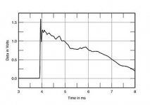
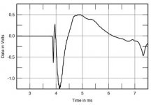
You can see that Dunlavy really focused on getting that step response as perfect as possible (and he made no secret of this on rec.audio)
I can't speak for David, but I'm under the impression that the Snell is optimized for vertical directivity. Basically it's a speaker with wide horizontal directivity and narrow verticaly directivity. This is the same goal that B&O and Revel pursue. Here's the vertical directivity of the Dunlavy and the Snell. Note that the Snell measurement goes out to +/- 20 degrees, while the Dunlavy measurement goes out to +/- 10 degrees. This difference makes it hard to see the difference in vertical directivity between the two, but you can see that the Snell is noticeably better.
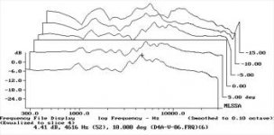
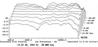
Here's the horizontal directivity of the Dunlavy:
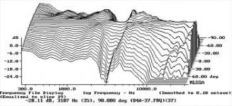
(Stereophile didn't publish one for the Snell.)
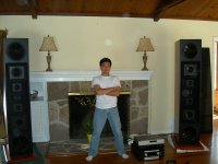
Long story short: yes, the two speakers LOOK similar. But Dunlavy was all about phase response, and it shows in the measurements. I believe Smith was after directivity, and you can see the difference in the measurements. (Hint: the tighter spacing of the Snell makes a difference.)
Hi Keyser,
I don't see anything wrong with that basic approach. Ground plane will work but of course you will need to tilt the array forward to get the mic axis roughly on center to the array. As the nearfield effects are so strong I would try and measure at a distance equal to your listening distance.
Averaging around a listening window is probably a good idea. Your C to C distance is about what we had with the McIntosh arrays and the HF "swishies" were noticeable at HF, at least with pink noise. They never bothered me on music, though. Some spatial averaging is appropriate.
One difference between ground plane and indoors will be the lack of the floor and ceiling planes. These "mirrors" give an infinite series of reflected virtual arrays, but they won't be there on ground plane. They probably don't make a huge difference but you may see a bass rise when you compare indoor curves to outdoor curves. (At low frequencies array extension will contribute coherent bass energy. At high frequencies, once the array is a certain length additional length doesn't add coherently, hence doesn't add level.
Show us your graphs when you have something!
David
Are you sure I should tilt the speaker? With an ordinary speaker that radiates a spherical wave-front, I understand. Yet a tall line-array (about 5.5 meters if you include the floor reflection) radiates a spherical wave-front at floor-level down to the low hundreds. If you were to tilt the array towards the microphone, I assume you'd no longer have a cylindrical wave-front.
Dave
I was thinking about this last night. If your line array has independent control over each driver then the spacing of the drivers is irrelevant - only the total distance matters, not the spacing. I can get any pattern I want (within the limits of the total length) with any spacing by shading the sources properly. Why log space if you don't need to?
I was thinking about this last night. If your line array has independent control over each driver then the spacing of the drivers is irrelevant - only the total distance matters, not the spacing. I can get any pattern I want (within the limits of the total length) with any spacing by shading the sources properly. Why log space if you don't need to?
Hi Keyser,
With all ground plane measurements you want to tilt the speaker to measure on the intended listening axis. Otherwise you will be measuring response on the arrays extreme edge. It may still have reasonable response there but that probably isn't your listening window.
Don't worry the array being at an odd angle to the ground, the ground isn't really there for your measurement since the microphone is at the bisecting plane. Thought of another way you will have two arrays in the measurements (and no ground plane) and it is okay to aim both arrays at the mic (bending them in the middle) to sample the center axis response. This may seem like a pair of bent cylinders but that makes no difference for the measurement. You will get the +6dB response expected, relative to the free space curve.
David
Dave
I was thinking about this last night. If your line array has independent control over each driver then the spacing of the drivers is irrelevant - only the total distance matters, not the spacing. I can get any pattern I want (within the limits of the total length) with any spacing by shading the sources properly. Why log space if you don't need to?
Glad to hear you are thinking about line arrays, although I can't help but feel like we are corrupting you.🙂
Shading gets any pattern you want at low frequencies (you can sample a pressure profile with any given number of points) but for higher frequencies then aliasing will come into play (the lobes) especially if the sample frequency (element spacing) is constant. Thought of another way, if we want a line with length proportionate to frequency and over a wide range we can either have high point density and long length (requiring lots of points) or concentrate points in the center for high frequencies and more sparsely for the extremes.
I like to think of it as a fractal-ish approach where 3 center elements are spaced and crossed over to blend without lobes. However we achieve that we can scale it up by some ratio and let the center trio become the center for the new group of 3 (including the added outer units). Then scale that up, add units, etc. I.e. log spacing.
Regards,
David
I have been dealing with line arrays for a long time. There is a full chapter in my book and if you will recall I sent a letter to the editor of AES about your paper on them. The fact that I don't really like them does not mean that I don't understand them.
Just after I wrote my comment I realized that the two line spacing's would alias differently. The log would smear the aliasing artifacts while they would be reinforced with a linear spacing. So yes, there is a difference at very high frequencies. But using an array way up to beyond its aliasing frequency seems to me to be hit or miss anyways. The individual drivers directivity would become important, even dominate and things would begin to fall apart (I would suspect) fairly rapidly. But I suspect that is what most of your design problems center on because below alias its a basically trivial problem.
Just after I wrote my comment I realized that the two line spacing's would alias differently. The log would smear the aliasing artifacts while they would be reinforced with a linear spacing. So yes, there is a difference at very high frequencies. But using an array way up to beyond its aliasing frequency seems to me to be hit or miss anyways. The individual drivers directivity would become important, even dominate and things would begin to fall apart (I would suspect) fairly rapidly. But I suspect that is what most of your design problems center on because below alias its a basically trivial problem.
Hi Keyser,
With all ground plane measurements you want to tilt the speaker to measure on the intended listening axis. Otherwise you will be measuring response on the arrays extreme edge. It may still have reasonable response there but that probably isn't your listening window.
Don't worry the array being at an odd angle to the ground, the ground isn't really there for your measurement since the microphone is at the bisecting plane. Thought of another way you will have two arrays in the measurements (and no ground plane) and it is okay to aim both arrays at the mic (bending them in the middle) to sample the center axis response. This may seem like a pair of bent cylinders but that makes no difference for the measurement. You will get the +6dB response expected, relative to the free space curve.
David
You are right of course. As long as the microphone is on the ground, it should work well. If the array is at an angle with the ground, it won't be possible to do a spatial average including movement in the vertical direction. Thanks!
Regards,
Martijn
- Status
- Not open for further replies.
- Home
- Loudspeakers
- Multi-Way
- Floor-to-ceiling array vs CBT