I have not had a convincing demo of any software that can accurately predict the BMR as point source, never mind as a line array or panel....
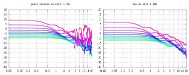
I cannot really simulate BMR because I have no idea how the membrane really behaves but I have compared a line source of 16 aligned point sources and something like your BMR16 simulated as continuous sources of 6cm diameter with 4cm between membranes.
Here on axis between 1 to 10m distance.
Last edited:
Extra data on a CSS BMR driver
Hi Jlo,
Thanks for trying, but that driver ( what is the spec?) looks pretty bad to me!
I am waiting on my first batch of production drivers ( Nov / Dec delivery) but until then could you use the CSS driver ( attached) as a test run?
The big difference is that the BMR produces the same horizontal and vertical dispersion / power response....So in a floor to ceiling line array mounted on the wall the array "floods" the room with a very natural balance of sound.
At a typical listening position of 3.5 to 4.5m there are no audible peaks or troughs anywhere....Even when one stands up and walks around the sound remains completely balanced.
Only when playing pink noise and placing your ear within 50cm to 60 cm of the array and then slowly crouching and standing can you hear the "woosh / wish" of comb filtering....With music / movies it is completely undetectable.
Is the data on the attached spec sheet enough to run an accurate sim?
The drivers are 112mm square chassis and are mounted edge to edge, so 112mm centre to centre spacing.
Thanks again for your time and effort
Derek.
Attachments
I cannot really simulate BMR because I have no idea how the membrane really behaves but I have compared a line source of 16 aligned point sources and something like your BMR16 simulated as continuous sources of 6cm diameter with 4cm between membranes.
BMR is really just another cone loudspeaker hiding behind a flat diaphragm. I'm sure the usual breakup modes still apply. Simulation via a series of point sources is probably the most realistic look at these.
All of these will show some form of aliasing as "sampled" versions of continuous line arrays. Even a series of tightly spaced ribbons will show some effect as they have a non-flat pressure profile along their length. Source density (lots of smaller units) is the answer unless you want to do something interesting such as a log spaced array.
David
Thanks!
Are you sure this apply to a virtually infinite line source as well? I guess so. Then there will be no such thing as a "cylindrical wave front".
All these approximations to continuous lines do have a cylindrical wave front, at least within limits. They fall in level 3dB per doubling of distance in their near field. Their near field extends a pretty good distance and past most listener positions. They have broad driver dependent horizontal dispersion and narrow array determined vertical dispersion. All characteristics of line arrays.
David
Please elaborate...
Hi Dave,
This is a bold statement....Please elaborate!
If you can prove this is true then how did the NXT inventors get such a broad range of patents granted?
Also if you can prove your statement, would I then be free to manufacture my own versions without paying them any royalties?
Thanks in advance
Derek.
BMR is really just another cone loudspeaker hiding behind a flat diaphragm. I'm sure the usual breakup modes still apply. Simulation via a series of point sources is probably the most realistic look at these.
Hi Dave,
This is a bold statement....Please elaborate!
If you can prove this is true then how did the NXT inventors get such a broad range of patents granted?
Also if you can prove your statement, would I then be free to manufacture my own versions without paying them any royalties?
Thanks in advance
Derek.
The driver I simulated is an ideal driver consisting of 49 point sources with each flat frequency response. The simulation of 16 drivers, 784 sources in a finite line, with some separation beetween drivers, gives the frequency responses of the picture. As Dave said, those curves are quite characteristic of line arrays.Thanks for trying, but that driver ( what is the spec?) looks pretty bad to me!
Thanks!
Are you sure this apply to a virtually infinite line source as well? I guess so. Then there will be no such thing as a "cylindrical wave front".
Jeno, sorry for adding confusion.
As Dave pointed out in another reply, the quasi infinite line source will have a cylindrical radiation pattern. Along a vertical line parallel to the line source the measured response will have constant magnitude and phase from "floor to ceiling".
What I am pointing out is that at any point along the "cylinder" the time domain response will not be a replica of the signal that is applied to the line source elements.
I haven't listened to one but I know of someone who has built one. It will help to shade the line regardless of the length.
Never having built a floor / ceiling array myself I would nonetheless agree with you.
I notice that you have applied ribbons in your line arrays. These have some inherent directivity in the vertical. I have a pair of R45s (Newform Research) in my setup. They employ 3 x 15" ribbon transducers in a stack. My thinking is that there is likely very little to no reason to shade these. They are crossed on the low side at 2 kHz.
Yes, I am familiar with the Newform ribbon and worked with them in a few systems several years ago. It would be interesting to see how they behave if shaded.
Jeno, sorry for adding confusion.
As Dave pointed out in another reply, the quasi infinite line source will have a cylindrical radiation pattern. Along a vertical line parallel to the line source the measured response will have constant magnitude and phase from "floor to ceiling".
What I am pointing out is that at any point along the "cylinder" the time domain response will not be a replica of the signal that is applied to the line source elements.
Thanks!
Yes, I am familiar with the Newform ribbon and worked with them in a few systems several years ago. It would be interesting to see how they behave if shaded.
Rick,
It will be a while before I tackle this one (it is difficult to get at the guts of an R45...first attempt resulted in damage) but I'm more than happy to share whatever I find when I get around to it.
The main problem with shading it is that the output will be lower and makes it more limited with matching to a line of woofers. I had mentioned several years ago to John (Newform) that he should look at a version with neo magnets to reduce the weight and possibly increase the sensitivity.
Hi Patrick,
Actually this will have 9 full range units of small size, so not a big speaker like the Snell XA. Not really going for state of the art but more seeing how to achieve more uniform directivity and polars with no side lobes.
We are using a lot of DSP and modest power chips on each element in our systems here. What's especially cool is arrays that radiate with 3 independent axis. (left center and right with L and R bouncing off the side walls) So that is a combination of end fire and broadside radiation in one cabinet via shared drivers. Most of the systems use a limited number of drivers with fairly uniform spacing so the side lobes can be higher than you want (and when you consider a side radiating axis, then the lobes will cross the couch position, not good).
Regards,
David
I had a question about the MTM array in your avatar, from the Snell XA90PS speaker. This morning I was doing some tinkering with MTM arrays and it appears that the "eXpanding Array" can be flipped on it's side.
The reason that I say this is because the spacing between the tweeter and the midrange is much tighter than in a conventional D'Appolito array; the spacing appears to be about one-third or one-half wavelength.
It looks like you could use some delay, adjustment of phase, or both to achieve a polar response that's basically free of vertical lobes.
And if you can do THAT, then you can flip the array on it's side.
Thoughts?
I'm picturing something like the eXpanding Array, but horizontal.
I took some inspiration from this interview here:
[Interview] David Smith [English]
"The eXpanding Array was a concept I came up with afterwards while at Snell. I suppose the systems were an evolution of work I had done on THX certification. THX was pushing higher vertical directivity but most of the licensees would just stack a pair of tweeters, or perhaps 2 tweeters and 2 woofers. The axial response could be fine and the directivity was higher, so room effects would diminish somewhat, but the response as you went off axis was a mess.
It was important to me that I achieve a system with smoother directivity and without the usual response nulls off axis. At Mac I did a THX system with 3 tweeters in a short row, not a line array so much as just a short multi-element array. If the center tweeter was used for its full range and the outer tweeters were progressively rolled off I could get something that was lobe free. It was directivity without “pain”. At Snell I just extended that over a number of sections and a wider frequency range. I was using Peter Shuck’s early Xopt crossover/system modeling software and was finding ways to stack elements tight and roll off each section in particular ways that gave very well behaved directivity. I found I could achieve flat response on axis, less than a dB or so droop at +-15 degrees vertical and a totally uniform 6dB or so shelving at +- 30-40 degrees. This was exceedingly well behaved. In essence, with the smooth transition from the inner tweeter to adjacent mids, to surrounding woofer, you are making a system that has an effective length proportionate to radiated wavelength. Looking for a marketing hook, we called it an eXpanding Array, meaning that its effective length expanded as you went down in frequency (that seemed more positive than it contracting as you go up in frequency!)
So with JBL I worked with constant directivity wave guide devices, at McIntosh with medium and long line arrays and at Snell with highly optimized symmetrical arrays. Of the 3 approaches I think the symmetrical array is best. Response is very well behaved and the directivity increase is about right, not as extreme as it is with the long arrays."
A picture is worth a thousand words, so I made one. <snip>
The Horbach Keele design is largely an evolution of the David Smith's Snell design. But I'm trying to figure out why the spacing is so much different.
So I thought I'd revisit my post from a few years back here.
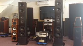
This is the Snell XA Reference Tower
In my post from a few years back, I'd stated that the center-to-center spacing was 16cm and the crossover was 2400Hz. I no longer believe that was accurate.
I believe the center to center spacing is 18cm and the crossover was 2400Hz. That's a small difference, but these arrays are really picky about their spacing, phase, and crossover. If you're off by even 10 or 20% it'll screw up your polars.
The reason that my spacing was off in the original post is because the Stereophile article stated that it was a 4.5" midrange. But I don't think this is the case; I believe it's a FIVE inch midrange, likely this:
https://www.falconacoustics.co.uk/downloads/Vifa/PL11WG09-08.pdf
The reason that I think this is because Vifa doesn't MAKE a 4.5" midrange! (AFAIK.) You would think that the "PL11" midrange would measure 11 centimeters, or 4.33", but it actually measures five inches across.
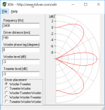
So the thing that I can't figure out is how the Snell works, when the side lobes are fairly nasty. The pic above shows what the vertical polars of the Snell look like, assuming a spacing of 18cm and a crossover of 2400Hz. The vertical beam is nice and narrow, but the side lobes are fairly brutal.
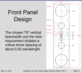
The Horbach Keele speaker uses a crossover that's virtually identical, but much tighter spacing. The tighter spacing reduces the severity of the side lobes of the array. (I believe the Snell spacing is 18cm; the Horbach-Keele spacing is 4.5cm.)
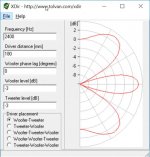
I think that animations are really handy to visualize this. The animation above shows what happens as the spacing gets tighter and tighter and tighter. The side lobes get less severe, and eventually the vertical beamwidth gets wider. But note that the units have to be REALLY tight for the vertical beamwidth to become particularly wide. Even with a spacing of just 25mm there's still a narrowing of the vertical beam.
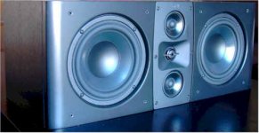
I can only speculate, but I'm guessing that David Smith was aware of these limitations, and may have been constrained by a lack of good small midranges. Twenty years ago, they were quite a rarity. That all changed as TVs got smaller and smaller and smaller and now we have a plethora of great 2-3" drivers.
The succeeding Snell speakers switched to a midrange that's half the size.
Good news, I answered my own question.
Here's an explanation:
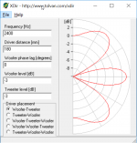
In the previous post, I wondered how the Snell speaker could function properly, when the spacing of the midranges indicated that it should have a vertical polar response like this. Obviously, this isn't so hot.
There's a clue in David Smith's Stereophile interview:
"The one breakthrough was finding a high-output, low-resonance tweeter from Audax that has a compact-diameter magnet structure. By rear-mounting this driver on a computer-cut aluminum MTM plate, the Vifa midrange units' driver baskets can overlap the tweeter's metal frame to keep the center-to-center spacings minimized."
So that was the part that I missed:
I was focused on the beamwidth of the dual midranges, but ignoring the contribution of the tweeter.
Understanding that difference, we get the following:
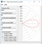
This is the response of the Snell MTM array at the crossover point. Nice and narrow.
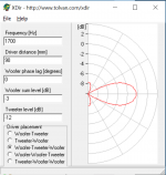
This is the response of the Snell MTM array at one half octave below the xover point. Still nice and narrow.
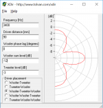
This is the response of the Snell MTM array at one half octave *above* the xover point. Things are starting to get weird here. Shaping of the response shape and the phase of the three drivers will be critical above the xover point.
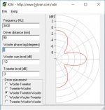
To help illustrate the last point, here's an animation that shows how the beamwidth changes when you vary the phase. It changes a LOT! I'm starting to understand why the Horbach Keele speaker uses FIR filters, it allows them to control the beamwidth by varying the phase. Back in the bad ol' days of passive crossover design, you would have to try a combination of crossover slope and physically delaying the radiation by setting back the tweeter to control this behavior. A real can of worms it looks like. Hooray for cheap DSP!
Here's some random things I learned today:
1) You can definitely control the beamwidth using an interference pattern generated by an array of drivers, but the polars get gnarly above the xover point. DSP is your friend.
2) The real eye opener for me was understanding that this type of design places some crazy demands on the tweeter. At the xover point, the tweeter is producing as much output as TWO midranges. So you need a beast of a tweeter or a high xover point. But another way to look at it is that you can get away with a smaller midrange than you might consider, because the weak link will likely be the tweeter anyways. IE, if we were making a two way loudsepaker we would never use a 2" driver for a midrange. But in the eXpanding array or the Horbach Keele array, the use of a 2" midrange isn't crazy. This is because the weak link is the tweeter. We're not going to be limited by our midrange. So we can get away with a smaller midrange than we normally might consider. This is particularly important since tight spacing really makes all of this a lot easier. Another reason to use small mids.
* Read more at Snell Acoustics XA Reference Tower loudspeaker | Stereophile.com
Here's an explanation:

In the previous post, I wondered how the Snell speaker could function properly, when the spacing of the midranges indicated that it should have a vertical polar response like this. Obviously, this isn't so hot.
There's a clue in David Smith's Stereophile interview:
"The one breakthrough was finding a high-output, low-resonance tweeter from Audax that has a compact-diameter magnet structure. By rear-mounting this driver on a computer-cut aluminum MTM plate, the Vifa midrange units' driver baskets can overlap the tweeter's metal frame to keep the center-to-center spacings minimized."
So that was the part that I missed:
I was focused on the beamwidth of the dual midranges, but ignoring the contribution of the tweeter.
Understanding that difference, we get the following:

This is the response of the Snell MTM array at the crossover point. Nice and narrow.

This is the response of the Snell MTM array at one half octave below the xover point. Still nice and narrow.

This is the response of the Snell MTM array at one half octave *above* the xover point. Things are starting to get weird here. Shaping of the response shape and the phase of the three drivers will be critical above the xover point.

To help illustrate the last point, here's an animation that shows how the beamwidth changes when you vary the phase. It changes a LOT! I'm starting to understand why the Horbach Keele speaker uses FIR filters, it allows them to control the beamwidth by varying the phase. Back in the bad ol' days of passive crossover design, you would have to try a combination of crossover slope and physically delaying the radiation by setting back the tweeter to control this behavior. A real can of worms it looks like. Hooray for cheap DSP!
Here's some random things I learned today:
1) You can definitely control the beamwidth using an interference pattern generated by an array of drivers, but the polars get gnarly above the xover point. DSP is your friend.
2) The real eye opener for me was understanding that this type of design places some crazy demands on the tweeter. At the xover point, the tweeter is producing as much output as TWO midranges. So you need a beast of a tweeter or a high xover point. But another way to look at it is that you can get away with a smaller midrange than you might consider, because the weak link will likely be the tweeter anyways. IE, if we were making a two way loudsepaker we would never use a 2" driver for a midrange. But in the eXpanding array or the Horbach Keele array, the use of a 2" midrange isn't crazy. This is because the weak link is the tweeter. We're not going to be limited by our midrange. So we can get away with a smaller midrange than we normally might consider. This is particularly important since tight spacing really makes all of this a lot easier. Another reason to use small mids.
* Read more at Snell Acoustics XA Reference Tower loudspeaker | Stereophile.com
Two years ago I had the pleasure to meet with David and his wife Melinda at their home and we listened to the two large Snells towers in his living room. If I remember correctly it did actually have quite small midrange drivers, 4" seems about right.
David told me he was most proud of the XA90's in his upstairs HT. They were in a smaller room though, and I generally have a harder time adapting to the acoustics of a smaller room, so I preferred the sound in the living room.
David is a very nice guy, but also an incredibly knowledgeable allround audio engineer. Too bad he hardly posts here anymore.
Ah, that's very interesting! He's worked for a ridiculously broad series of loudspeaker manufacturers. The fact that his reference speakers are the Snells of his own design says quite a lot.
(For anyone that isn't aware, Speakerdave has worked at JBL, Snell, Mcintosh, PSB and Bose.)
(For anyone that isn't aware, Speakerdave has worked at JBL, Snell, Mcintosh, PSB and Bose.)
Jeno, sorry for adding confusion.
As Dave pointed out in another reply, the quasi infinite line source will have a cylindrical radiation pattern. Along a vertical line parallel to the line source the measured response will have constant magnitude and phase from "floor to ceiling".
What I am pointing out is that at any point along the "cylinder" the time domain response will not be a replica of the signal that is applied to the line source elements.
Very well said 🙂
A few years ago, i derived the frequency-domain pressure response of an infinite line source, at a radial distance "r" from the line (which, of course, had already been done by countless others), revealing the well-known 3dB drop with doubling frequency, or doubling distance.
By Inverse Fourier Transform, i then derived the time-domain impulse response, h[t], of an infinite line source :
h[t] = k*{u[t - (r/c)]}/{sqrt[t^2 - (r/c)^2]}
where:
u[t] is the classic unit-step function
"r" is the radial distance from the line
"c" is the speed of sound
"k" is a constant (air density/2pi)
i'm pretty sure it's correct 😉 Perhaps i'll start a new thread on the topic, if there's any interest 🙂
Last edited:
werewolf,
I would be interested in your efforts and I'm sure that others would follow along. Though the more your work can be linked to practical arrays the better.
Jim
I would be interested in your efforts and I'm sure that others would follow along. Though the more your work can be linked to practical arrays the better.
Jim
Well that's all the motivation I need! May wait until after Thanksgiving, to begin.
Sadly, mostly everything i've done in audio for the past several years has been mostly theoretical, in nature 🙁 BUT, the floor-to-ceiling line array (with appropriate drivers and spacing, positioned between reflective floor and ceiling) does a decent job of approximating an infinite line source ... so the theoretical results are quite relevant, i think.
Sadly, mostly everything i've done in audio for the past several years has been mostly theoretical, in nature 🙁 BUT, the floor-to-ceiling line array (with appropriate drivers and spacing, positioned between reflective floor and ceiling) does a decent job of approximating an infinite line source ... so the theoretical results are quite relevant, i think.
Last edited:
- Status
- Not open for further replies.
- Home
- Loudspeakers
- Multi-Way
- Floor-to-ceiling array vs CBT