There are in fact ways to do measurements in reflective spaces that completly ignore reflections (See Weinreich in ASA about 50 years ago).
Earl, is this what you're referring to?
Cookies Required
I've personally never seen such a test set up? Is it used in industry? The apparatus seems complicated and costly.
I think a good old ladder outdoors, spliced to near field is the quickest solution.
Dave
How to know which resonance is audible?
I recommend the JAES Olive studies on resonance audibility, and delayed resonance audibility, very useful to answer this question. It's not as simple as using critical bands.
Just for that reason responses should be presented in a time-freq resolution that mathces the ear.
- Elias
I'm familiar with it, I've taken thousands of telecom measurements that averaged in critical bands
Auditory scales of frequency representation
Its too much smoothing for high definition audio. Roughness can be caused by two tonal components in a critical band, any high q peaks can lead to increased roughness.
Dave
Why not just use a directional mic?
This looks like the bees knees:
Time Dilation, Part 2 Page 3 | Stereophile.com
Haven't tried it yet but if I get back into do a lot of measuring, I'll be whipping up the soldering iron.
Dave
Earl, is this what you're referring to?
Cookies Required
I've personally never seen such a test set up? Is it used in industry? The apparatus seems complicated and costly.
I think a good old ladder outdoors, spliced to near field is the quickest solution.
Dave
That is not the "first" paper, but it is based on it. That paper is an application of the technique as defined in the first paper.
No, its not easy and its not very practicle and thats why you don't see it arround. The point was simply to show that it is not impossible as has been suggested.
That said, I actually use a modification of this same technique in my software, so for me its not that hard and I would like to try it. I do expand the field into spherical harmonics by fitting the data to those. This has many advantages. First it gives me an infinite spatial resolution even though the data has a fairly course amount. Second I can take the data to any radius, i.e. true far-field or most interesting the extreme near field. I have software that will actually plot out the velocity distribution at the source from far field data. This is how I know what causes the axial holes in my responses - I can see the diffraction at the waveguide edges in reconstructions of the waveform right at the mouth of the waveguide.
To impliment the referenced technique I really just need to do the polars at a second radius. With the two data sets I can exclude the reflections - in principle. The problem, or not, I do not know yet, is that I only do a single plane. This is not a problem for horizontal polars, and certainly horizontal reflections, but I am not sure what would happen with vertical reflections. That could be an issue. I just do not know yet.
This looks like the bees knees:
Time Dilation, Part 2 Page 3 | Stereophile.com
Haven't tried it yet but if I get back into do a lot of measuring, I'll be whipping up the soldering iron.
Dave
I have investigated Eric Benjamins method in depth and concluded that it really isn't any better or more stable than nearfield. It has some pros and some cons just as near field, but, to me, it was a wash. I have combined nearfield with my Spherical Harmonic approach with some success, but too little experince to have any conclusions at this point.
That is not the "first" paper, but it is based on it. That paper is an application of the technique as defined in the first paper.
I haven't read the papers, but if measured at one radius, are any assumptions required regarding the source size and resultant polars?
Dave
I have investigated Eric Benjamins method in depth and concluded that it really isn't any better or more stable than nearfield. It has some pros and some cons just as near field, but, to me, it was a wash. I have combined nearfield with my Spherical Harmonic approach with some success, but too little experince to have any conclusions at this point.
Thanks for sharing your tests here. I'm using NF spliced with a diffraction model, then with excess phase removed, min phase calculated with Hilbert, then excess phase re-added, equivalent to that of the gated measure, at the splice frequency. Wish I still had an anechoic chamber to compare to, but I have pretty good faith in the diffraction models below 300Hz. The wavelengths are long enough that the error should be pretty darn low.
What was the con with Benjamin's method? SNR at higher frequencies?
Dave
In the spherical harmonics expansion you are assuming that the source is a sphere. You will get back what the sphere would need to be to create the field that was measured. If the sphere is slightly larger than the source then you get a decent resolution, but not perfect. Basically its much like radar. You can get details down to about a half wavelength, but below that requires very advanced techniques (like those used in electronic microscopy).
The Benjamin apparoach requires an assumption of the LF shape. The better this assumption the better the technique works and one can always converge on the answer with iteration. Near field requires no prior assumptions and it too can get better resolution with iterations or, in my case, nearfield polar angles.
The point is that its all down to signal processing. The discussions of microphone techniques are small improvements in SNR, but its signal processing that can really pull out the data from the garbage.
I like having anechoic measurements to know what the speaker does without room influence. But I also like to know what the speaker will do when installed as intended,
Another venture back to the practical versus the scientific. It almost warrants a sub thread but still on topic, I think.
I cite an earlier discussion on weighting of the measured power response given the known condition of absorbers being used. I could fairly assume that if sound is being absorbed then it is no longer a part of the real power response.
I think it would be stretching the point though to invert this claim to include reflections in the 'new' power response as they are smeared in time and no longer valid.
Therefore, I think that as long as reflections are kept out, an in room response can be useful...especially for we DIY that have the luxury of knowing the intended final application of our speakers.
I think that the best approach is a combination of things. The room refelctions should be included in some frequency ranges, but not others. For example, there is no "direct field" at LFs in the sense that we can actually process these frequencies fast enough to exclude the reflections, its all steady state down low. But we can process higher freqs fast enough to exclude many of the reflections, so they should not be included as that gives a false picture. The problem is that the "integration" time varies with frequency and this is hard to do in a way that is truely accurate.
Holm does something like this, but its far too narrow at HFs where the integration time is longer than several periods, and its probably too narrow at LFs where the integration time is at least several periods and can get very long even going to infinity - certainly longer than the reverberation time.
I have done measurements fixed at 10 ms and this is attractive, but admittedly not ideal.
I have done measurements fixed at 10 ms and this is attractive, but admittedly not ideal.
I would think that the window size should be fixed at the best resolution possible down to the lowest frequency possible, and then the window be made progressively larger only at frequencies lower than this.
At first blush, it would make sense to adapt Elias' critical band idea and open up the low frequency window so as to have frequency band resolution equal the critical bandwidth, but only in the low frequencies. So at 50 Hz, the bin size is the same as the critical bandwidth at 50 Hz or better. At 160 Hz its the critical bandwidth at 160 Hz or better, etc.
This still results in much more smoothing than the near field technique and won't capture resonances (room or speaker) that well, but it does capture broadly the tonal balance in the low frequencies, due to room contribution.
Dave
I second that.I think that the best approach is a combination of things. The room refelctions should be included in some frequency ranges, but not others. For example, there is no "direct field" at LFs in the sense that we can actually process these frequencies fast enough to exclude the reflections, its all steady state down low. But we can process higher freqs fast enough to exclude many of the reflections, so they should not be included as that gives a false picture. The problem is that the "integration" time varies with frequency and this is hard to do in a way that is truely accurate.
I came to the same idea when considering the "Haas effect".
Hi,
I've implemented the Bark approach in time-freq domain with wavelets.
Here's a response of an ideal impulse:
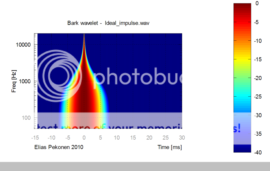
- Elias
I've implemented the Bark approach in time-freq domain with wavelets.
Here's a response of an ideal impulse:
- Elias
Member
Joined 2003
I would think that the window size should be fixed at the best resolution possible down to the lowest frequency possible, and then the window be made progressively larger only at frequencies lower than this.
That is what I have been doing, but sure would like to try the Benjamin method.
The problem is that the "integration" time varies with frequency and this is hard to do in a way that is truely accurate.
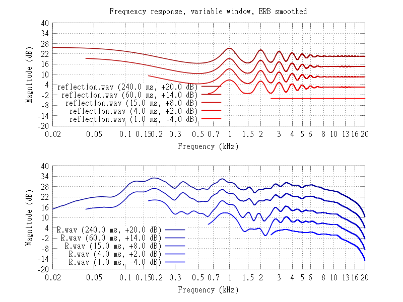
you can also use various gating time on same graph :
here you see and ideal reflection after 1ms and a real speaker measurement showing reflections building up between 3 and 5kHz after the first ms.
Last edited:
Or see everything in one time-freq plot. Here a row of ideal decaying reflections at 1ms intervals:
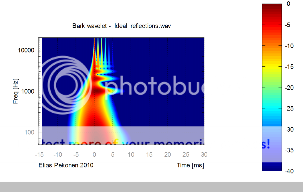
- Elias
- Elias
I would think that the window size should be fixed at the best resolution possible down to the lowest frequency possible, and then the window be made progressively larger only at frequencies lower than this.
Dave
I think that our messages are getting crossed. For designing a speaker, yes, I want the widest window that I can get. I was responding to the kinds of measurements that one might want to make in-situ to include the room and how the speaker works in that situation. In that case the window is not a fixed thing and not as wide as possible, but the goal is different.
you can also use various gating time on same graph :
here you see and ideal reflection after 1ms and a real speaker measurement showing reflections building up between 3 and 5kHz after the first ms.
It would be better to have a single line however. Thats more difficult, but not impossible. I've considered doing it before.
Graph of the number of periods for frequency detection from Rossing 1989:
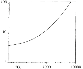
I took an old piece of data I had on the hard drive and gated it at 100 ms--the amount of time it takes to just hear a pitch at 20 Hz if you extrapolate that Rossing graph conservatively:
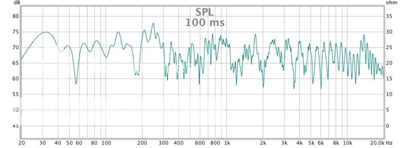
Now w/o a gate:

The biggest difference you see is actually a problem of graph resolution d/t the loss of data points in the bass. Keep in mind that's over 3 times the length of the Haas limit and looking at the equal loudness curves (not correct for music) we just don't hear bass well.
I can see why the experts say steady state is what you hear in the bass. Extracting irrefutable proof--I don't know how. The evidence I have is clearly headed in one direction--we certainly don't have time resolution at bass frequencies like we do midrange and treble.
Look at the graph for the 50 Hz time. You'll see the same shape just at less resolution/data points.

Anyway, it's either steady state, or darn close to.
One thing about bass decay; theoretically the decay could be so fast you would never hear the bass. I wonder if that's the case with the outdoor concert bass people perceive as fast--maybe they're just hearing the midbass while feeling the deep bass go right through them? 'Sounds' reasonable to me.
Dan
I took an old piece of data I had on the hard drive and gated it at 100 ms--the amount of time it takes to just hear a pitch at 20 Hz if you extrapolate that Rossing graph conservatively:
Now w/o a gate:
The biggest difference you see is actually a problem of graph resolution d/t the loss of data points in the bass. Keep in mind that's over 3 times the length of the Haas limit and looking at the equal loudness curves (not correct for music) we just don't hear bass well.
I can see why the experts say steady state is what you hear in the bass. Extracting irrefutable proof--I don't know how. The evidence I have is clearly headed in one direction--we certainly don't have time resolution at bass frequencies like we do midrange and treble.
Look at the graph for the 50 Hz time. You'll see the same shape just at less resolution/data points.
Anyway, it's either steady state, or darn close to.
One thing about bass decay; theoretically the decay could be so fast you would never hear the bass. I wonder if that's the case with the outdoor concert bass people perceive as fast--maybe they're just hearing the midbass while feeling the deep bass go right through them? 'Sounds' reasonable to me.
Dan
- Status
- Not open for further replies.
- Home
- Loudspeakers
- Multi-Way
- 'Flat' is not correct for a stereo system ?