I say that because you mentioned an earlier model of the tweeter filter so, at first, I was wondering whether my units were of a ‘transition’ period when they were still using the old filter on the tweeters but on ‘new’ schematic pcbs.
but if my units are in fact more recent they might have had a reason to revert to the old tweeter filter
but if my units are in fact more recent they might have had a reason to revert to the old tweeter filter
You might get your hands on some crocodile clip leads.I haven’t got a decent soldering iron at hand right now
in my opinion also the 100uF Hitano bipolar cap in the midrange circuit has been put there afterwards. this does not look like KEF factory.
I would not populate the positions that have never been populated, KEF had a reason not to put anything there. Maybe your drivers measure(d) exceptionally well.
If the person who swapped capacitors has used a combination of caps with the inductor that does not achieve the intended crossover point, then caps with the right values should be used. But who knows which value the tweeter inductor L7 in your crossover has?
For crossover parts I use different speaker DIY webshops in Europe. Send me a PN and I can provide some addresses.
I think differing parts on the crossovers do not represent "generations" or iterations of a speaker model but reflect KEF's goal to roll out individual speakers which all measure identically flat. Sometimes this required adding extra parts (soldering a tiny cap in parallel to a bigger one), sometimes omitting parts. In your case not so many correction elements (as the Zobel C13-R3) were needed – that's how I interpret it.I say that because you mentioned an earlier model of the tweeter filter so, at first, I was wondering whether my units were of a ‘transition’ period when they were still using the old filter on the tweeters but on ‘new’ schematic pcbs.
but if my units are in fact more recent they might have had a reason to revert to the old tweeter filter
But the driver specs may have changed with time too.
In my experience getting your xovers to optimal function will need some trial and error. swapping parts untll it sounds right (and/or measures well).
of course, the 100uF should be replaced too as it wasn’t original (and … well… the cheapest by mundorf rated 100uF is 50€ …).
regarding the inductor, you can see the the top two inductors in your xo are way larger then on mine (so mine could well be .25 instead of .35)
regarding some parts… I checked the f&t ones and they all seem to be of pretty high tolerance (20%). is that correct..?
regarding the inductor, you can see the the top two inductors in your xo are way larger then on mine (so mine could well be .25 instead of .35)
regarding some parts… I checked the f&t ones and they all seem to be of pretty high tolerance (20%). is that correct..?
Last edited:
50€ for one cap? do you mean 5€? I see a Mundorf 100uF raw, 100V rated, for 4,80€ at lautsprechershop.
The two inductors on top of the board in the photo you refer to are in the midrange circuit. Their shapes are longer on my crossover, but wider on yours. Thicker or longer doesn't matter to achieve the same value. They will be about the same spec, with possible changes in the % deviation, which KEF matched.
Bipolars are sold as 20% tolerance usually. those you mentioned will be much closer to the value printed on them. you could also select them by hand from a larger batch. but as we don't know in which tolerance range KEF selected them for your board, it is futile to get extremely close to the value on the schematic. and don't forget that the drivers will have drifted in specs, too.
The shop I mentioned above has sold out the plain 3.3uF bipolars, but you'll find them at darisusgmbh or elpro for example. they cost in the 1,50€ range.
I meant the 100uF Mcap Mundorf makes.50€ for one cap?
that's an Ecap, I guess..? not Mcap..?I see a Mundorf 100uF raw, 100V rated, for 4,80€
Sure, size and shape of the inductor don't say much about its value…
you mean the f&t..?Bipolars are sold as 20% tolerance usYetually. those you mentioned will be much closer to the value printed on them.
I agree. BUT:but as we don't know in which tolerance range KEF selected them for your board, it is futile to get extremely close to the value on the schematic
actually the xo of the OP of this thread is exactly like mine, same missing components (C11, C13, R3, etc).
on his board C10 and C13 read as per schematic (3.3 and 7uF). that means that in parallel they measure to L7 roughly as 10uF which is
in line with what you mentioned about early tweeter filters (2 x 5uF caps).
Yet C11 in place before C12 is actually in series and should lower C12's value (to something lower than .22uF) or am I wrong..?
That means that, using the values as per schematic, the parallel capacitors going to L7 would read together about 3.5uF..?
Attachments
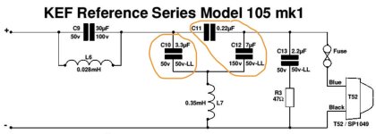
C10, L7, C12 form a third order high pass filter. C11 just bypasses it a little.

thank you.C10, L7, C12 form a third order high pass filter. C11 just bypasses it a little.
still it should make a difference to send to L7 through C12 (7uF) only after C11, I guess..?
in my current board C12 is 4.7uF (C10 maybe too, no marking on that, but should be if @eschenborn is correct: 2 x 5uF)
1. Drawing it differently can sometimes show the situation better.
2. 220nF is a small amount. Here is a guide to the difference in response.

2. 220nF is a small amount. Here is a guide to the difference in response.
thank you.
still the dilemma is that in the highs section of my xo the parts crossed in red have never been present:

on top of that C12 is now 4.7uF (C10 too, maybe..?)
still the dilemma is that in the highs section of my xo the parts crossed in red have never been present:
on top of that C12 is now 4.7uF (C10 too, maybe..?)
😀
yes, sorry.
long story short:
I am not sure what values C10 and C12 should be considering that they are now not original (probably two 4.7uF) and my unit never came with C9, C11, C13 and R3.
yes, sorry.
long story short:
I am not sure what values C10 and C12 should be considering that they are now not original (probably two 4.7uF) and my unit never came with C9, C11, C13 and R3.
Here is someone over at audiokarma who made sort of the same find:
https://audiokarma.org/forums/index.php?threads/kef-105-1-recap-experience.565332/
he found C12 to be 3,3uF same as C10.
we will never know what was on your original crossover.
we do know that the wholly populated crossover with the original values and the right types of caps yields a great sounding speaker – although maybe not as well matched as yours was when it left the factory, by omission of certain elements.
fully populating your crossover would take you a long way toward the right sound.
otherwise you'd need to try what works. 3.3uF plain bipolar for C10, 6.8uf raw bipolar for C12, and a small 0.22uF WIMA mkp4 for C11 should get you close to the right sound balance, too.
there will be some listening and tweaking needed anyway – even when you fully populate it. I've been there already.
in your place I'd buy a good soldering iron tomorrow, order some caps, and start.
yes, those are indeed the facts.
thanks for the input.
why would you pick a raw one for C12 (aren’t both 10 and 12 supposed to be LL..?)
thanks for the input.
why would you pick a raw one for C12 (aren’t both 10 and 12 supposed to be LL..?)
we do know that the wholly populated crossover with the original values and the right types of caps yields a great sounding speaker – although maybe not as well matched as yours was when it left the factory, by omission of certain elements.
also, just in terms of historical facts, it appears (as I said above) that my xo follows the same 'stripped down' scheme of the one in the units of the OP of this thread. so, it seems, they must have alternatively used that circuit in more units in place of the (newer..?) one the pcb would expect
for sake of general interest, here a graph of the response of the tweeter filter (provided I used the software the right way).

in red the curve of the full xo as in @eschenborn 's units. in blue the one in my unit. the highest peak is around 3.6Khz and just moves down towards a lower frequency using 5uF caps for C10 and C12
in red the curve of the full xo as in @eschenborn 's units. in blue the one in my unit. the highest peak is around 3.6Khz and just moves down towards a lower frequency using 5uF caps for C10 and C12
I wanted to add that, following the graph, I tried to 'balance' the sound (which I was often doing anyway because I found the speakers too bright) with a graphic eq and, to my opinion, in a very quick-and-dirty test they do sound way more balanced.
no, I repeat it is not a question of newer and older versions, it is a question of how to achieve greatest linearity. see my post #54also, just in terms of historical facts, it appears (as I said above) that my xo follows the same 'stripped down' scheme of the one in the units of the OP of this thread. so, it seems, they must have alternatively used that circuit in more units in place of the (newer..?) one the pcb would expect
- Home
- Loudspeakers
- Multi-Way
- Fixing molested crossover in KEF 105