I mean a “plain”, aka “low loss”, LL, in Alcap speak, bipolar electrolytic cap. Plain, smooth foil, not the perforated, rough one of standard bipolars.you mean … Mcap..? (they otherwise use very fancy names: supreme, classic, etc 😀 )
Mundorf has them, they are made by Fischer & Tausche. Fischer & Tausche sell them as well directly, series “ATBIG”.
For a while Falcon used exactly these bipolar caps as replacements for ALCAPS. There is even “ATBIG” printed on them, curiously, together with ALCAP. “ATBI” without a G is the Fischer & Tausche series with rough foil. Mundorf calls those “rough”, the others “plain”, respectively.
i’m only talking about electrolytic capacitors, not about any type of film capacitor here. probably, if you use a film capacitor, either plain MCap or some other stuff, you would need to attenuate the treble level with a small resistor in series.
but then more things in the crossover will start to change, so best to try to get away with the right bipolar at the input.
Last edited:
thank you again.
I am temped to replace some of the non-original caps in the xo filter to tame the highs…
fact is… those caps now in place seem not to follow the schematic as published in this post (next to that, I am pretty sure kef would match cap values per unit so … veer from their own ‘official’ values for each specific case).
is there an alternative schematic of the xo filter or can anybody confirm that one, at least..?
Ciao l'uomotigre,
just restore the original crossovers with the right sort of caps and all will be well.
at the present moment your crossovers are wrong, so the speakers sound off.
the schematic of the Ref 105.1 crossover in post #1 of this thread is correct.
just restore the original crossovers with the right sort of caps and all will be well.
at the present moment your crossovers are wrong, so the speakers sound off.
the schematic of the Ref 105.1 crossover in post #1 of this thread is correct.
@eschenborn
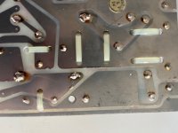
your suggestions sounds logic and good yet … on the original boards of my units many parts were simply not there
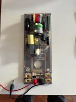
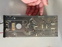
straight out of the factory (see image).
that'd make for very different values in the caps, I'd think..?
this is how the xo for the tweeter came (crossed red parts have never been there):

your suggestions sounds logic and good yet … on the original boards of my units many parts were simply not there
straight out of the factory (see image).
that'd make for very different values in the caps, I'd think..?
this is how the xo for the tweeter came (crossed red parts have never been there):
Interesting! that’s one of the KEF enigmas. I’ve heard about it already (must be some thread here). Can you be sure that the left out positions are virgin? Then I’d just substitute what was there with the right material.
yes, although that'll take some fiddling because the board is attached behind the twisting support of the head.
yet… I'd expect the values of the parallel caps to definitely be different..? considering they do not follow any cap on the input line..?
yet… I'd expect the values of the parallel caps to definitely be different..? considering they do not follow any cap on the input line..?
freeing the crossover board is some work, but it is pretty much self explaining and not too complicated. Your start by screwing out the knob which tilts the head. Don’t lose the screws, and don’t lose these oh so many washers.
I did not understand your question in the second part of your post.
I did not understand your question in the second part of your post.
I meant that since in my xo c9, 11 and 13 are absent, c10 and 12 might indeed differ in value from the schematic.
L7 gets, per schematics and in paralllel, c9+c10 and c9+c11+c12 … right..?
L7 gets, per schematics and in paralllel, c9+c10 and c9+c11+c12 … right..?
you will have to see what values you'll find there and then replace those values with new components with the same values.
KEF matched the choice of components to the driver characteristics. of course those might have slightly drifted over time.
KEF matched the choice of components to the driver characteristics. of course those might have slightly drifted over time.
C11 doesn't have a large effect. C13 and R3 do pull the treble down a little, since you mention there being too much. The notch with C9 appears a little dramatic, but I'm only looking from a distance.
On the other hand a few ohms just before the tweeter gives you another route to lowering the treble.
On the other hand a few ohms just before the tweeter gives you another route to lowering the treble.

Good morning, ah, and one thing comes to my mind: Changes to the different sections of a filter to my experience can have effects upstream or downstream... something done to the midrange part of the crossover can manifest as "more treble" in the tweeter section.
As I found, that parallel cap C6 was very influential. If a cap with a lower ESR than the original one has been put there, replacement with a more similar-spec'ed bipolar – or the addition of a small value resistor (1-2 ohms) in series – might help.
In other words: I am curious to see a shot of your actual crossover, once you dug it out of the head assembly 🙂 Unfortunately I have screwed all back into place just a short time ago and so far did not find my own photos.

hi luomotigre,
thanks. interesting. so the mid section is untouched apart from C7 where for some reason a lower-quality cap was used. This Hitano cap is not original. It also has the wrong specification it should be 100V. this can be changed with a Mundorf raw bipolar.
Is cap C6, the black 10MFD Elcap on the right side of the photo, fully attached, or is the lower lead to the PCP broken? I can't see it clearly on the photo.
This is how mine looked before recap:
C10 is a low loss ("plain") type, C12 is not, it is "raw"/ "rough" bipolar electrolytic.
On my crossover C7 is also only 50V, factory built. Confusing stuff. I am sure they hand-picked what gave the flattest response.

C10 is a low loss ("plain") type, C12 is not, it is "raw"/ "rough" bipolar electrolytic.
On my crossover C7 is also only 50V, factory built. Confusing stuff. I am sure they hand-picked what gave the flattest response.
Last edited:
hi,
the 10uF is attached, it’s just skewed in place to fit the inductor on its left which, in my xo, is wider than yours.
the grey cap is rated 4.7K (4.7uF ?) at 250V. the yellow one above it I can’t read (marked on the other side..?)
the 10uF is attached, it’s just skewed in place to fit the inductor on its left which, in my xo, is wider than yours.
the grey cap is rated 4.7K (4.7uF ?) at 250V. the yellow one above it I can’t read (marked on the other side..?)
thank you.
The other capacitor is possibly also 4.7uF. I am very curious to know the value. Couldn’t you quickly unsolder it on one side and look? The very simple tweeter circuit in old KEF speakers was two 5uF capacitors, and between them an inductor of 0.25mH to ground. As the inductor (here 0.35mH) has not been changed, if both caps are 4.7, the inductor is of a drastically wrong value. But we need to know the value of the yellow capacitor in order to understand this 🙂
The other capacitor is possibly also 4.7uF. I am very curious to know the value. Couldn’t you quickly unsolder it on one side and look? The very simple tweeter circuit in old KEF speakers was two 5uF capacitors, and between them an inductor of 0.25mH to ground. As the inductor (here 0.35mH) has not been changed, if both caps are 4.7, the inductor is of a drastically wrong value. But we need to know the value of the yellow capacitor in order to understand this 🙂
Last edited:
anyway I think you can be sure that your speakers will sound great after you corrected all these weird changes
@eschenborn
I haven’t got a decent soldering iron at hand right now to resolder the cap. I’ll let you know.
as I said, the xo (except for the replaced parts) is just straight out of factory (with only the two caps going into the inductor).
so … adding the missing parts seems a bit random..?
btw, where do you source your parts?
- Home
- Loudspeakers
- Multi-Way
- Fixing molested crossover in KEF 105