AI and correct information...😏 funny guy.
You'll probably get a schematic for a washing machine with a speaker hooked up where the motor should be. 🤓
You'll probably get a schematic for a washing machine with a speaker hooked up where the motor should be. 🤓


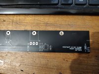
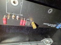
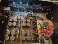
Here are some photos.
and, for later, when you succeed with making amp functional: I see you have cap-multipliers ........ and no big caps after
you must have at least 10000uF per rail after cap multiplier, to ensure dynamic reserve ......
This is a builders thread for the "long and skinny" J2 clone boards.
Please post hints, tips, discoveries, etc. And of course pictures. 🙂
Please post hints, tips, discoveries, etc. And of course pictures. 🙂
Docs in first post…I am not a robot 🤪
Yes, that is what a robot would say, isn't it...I am not a robot
Just FYI, the links in first post all say 'file not found'.
...but my clothes sound FANTASTIC!a washing machine
All links work for meYes, that is what a robot would say, isn't it...
Just FYI, the links in first post all say 'file not found'.
I think I upset chatGPT and it is now taking revenge.... dammit, I knew it.All links work for me
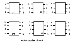
U1 is most likely stuffed backwards
Attachments
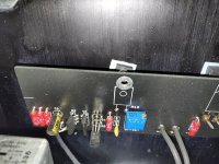
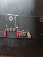
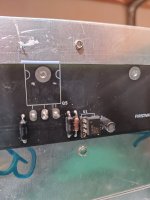
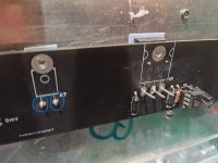
Quindi proverò a rispondere allegando alcune immagini, il 4n35 è su uno zoccolo da cui sono stati rimossi due pin e ho controllato di nuovo ed è inserito e posizionato come quello nel mio J2 funzionante (ma senza zoccolo), le schede sono di Jeff Young (gerber) e l'alimentatore sarà come quello nel J2 funzionante.
Attachments
-
 IMG_20250521_142351465.jpg702.4 KB · Views: 67
 -
 IMG_20250521_141958251_HDR.jpg404.2 KB · Views: 64
 -
 IMG_20250521_141931741.jpg533.1 KB · Views: 84
 -
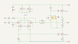 Immagine 2025-05-21 141520.png19.7 KB · Views: 86
 -
 IMG_20250521_140922298.jpg701.7 KB · Views: 82
 -
 IMG_20250521_140841688.jpg326.6 KB · Views: 63
 -
 IMG_20250520_165328792.jpg269.8 KB · Views: 63
So I'll try to answer by attaching some images, the 4n35 is on a socket from which two pins have been removed and I checked again and it is inserted and positioned like the one in my working J2 (but without a socket), the boards are from Jeff Young (gerber) and the power supply will be like the one in the working J2.
![IMG_20250521_144518254_HDR[1].jpg](/community/data/attachments/1371/1371279-5586f8d80576f68e724be3f39c512ff5.jpg?hash=u-2jqrCcdH)
the boards are from Jeff Young
Nature of things, I believe it's completely normal to take all these questions to thread where that project is presented
anyhow, what you need to measure and present is:
- confirmation that there is no short between outputs and heatsink
- confirmation of rail voltages
- voltages across fat resistors in output stage (R7, R8, R10)
- voltage across P1 and note of its setting ( maxed or not)
- DC Offset voltage
while measuring everything, work at one channel at time (second disconnected from PSU), inputs shorted to GND, no load at output
- Home
- Amplifiers
- Pass Labs
- FirstWatt J2