Looking good spades! Thanks for posting the pictures, and for the kind words about the boards. I am glad you are so pleased with the end result.
Happy Thanksgiving!
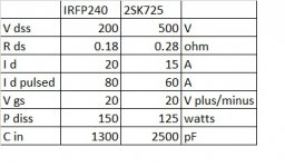
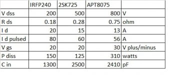
Gents, specially Nelson, I have a question. When I was going through the drawers of used parts, I discovered few APT8075BN N-ch mosfets. Could these be used in F1? They are high voltage, I know.
Gents, specially Nelson, I have a question. When I was going through the drawers of used parts, I discovered few APT8075BN N-ch mosfets. Could these be used in F1? They are high voltage, I know.
Rds for SJEP120R100 is 0.08ohm, for the IRFP240 its 0.18ohm, and the APT8075 has Rds all the way up at 0.75ohm. Ok that is not good. No point in trying. Thanks.
I look forward to your final details Chas, once you have tested the new F1J version thanks as you have posted in the thread in the GB section.
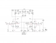
You can reduce Source resistors on F1 (assuming you have them) to make up for
lower Rds. Me, I don't get excited - install, measure, listen. Maybe it will sound good.

lower Rds. Me, I don't get excited - install, measure, listen. Maybe it will sound good.
ifference between various types - looking at output nodes DC potential, can only be as big as is difference between their Ugs voltages for chosen Iq
so, few volts max - hardly being of any significance
however, if you really want to adjust that, go for it
though, I would go for changing upper (or lower) 47K with , say, cell of 43K fixed+10K trimpot, rather than using just one coarse adjustable trimpot (47K or 50K)
so, few volts max - hardly being of any significance
however, if you really want to adjust that, go for it
though, I would go for changing upper (or lower) 47K with , say, cell of 43K fixed+10K trimpot, rather than using just one coarse adjustable trimpot (47K or 50K)
yup, the mod works great
it allows me to adjust output dc and voltage on the input gate at the same time
i can now report that all three mosfets work great, of course, just listening on test speakers, but the sound is nice whatever the pair
previously, when I soldered parallel resistors to adjust DC, I had to remove them and start all over with different mosfets
now with trimpots on both sides, no soldering, just adjust the trimmer
i have three sets of outputs on the separate heatsinks, so its easy
it would be even better to put some 3prong connector there, will see
ifference between various types - looking at output nodes DC potential, can only be as big as is difference between their Ugs voltages for chosen Iq
so, few volts max - hardly being of any significance
however, if you really want to adjust that, go for it
though, I would go for changing upper (or lower) 47K with , say, cell of 43K fixed+10K trimpot, rather than using just one coarse adjustable trimpot (47K or 50K)
so you are suggesting four trimpots? naaah, too messy
ok that's what Chas did, and it works too, I just needed more freedom
if I get a chance, I will try to compare distortion by RightMark Audio Analyzer
but I may work on Aleph J first
if I get a chance, I will try to compare distortion by RightMark Audio Analyzer
but I may work on Aleph J first
I had time to measure distortion with all three mosfets I used. It was tricky at first, because F1 has no ground on speaker outputs, its lifted ~8 volts above the input signal ground, so connecting the wires to soundcard could cause the trouble. Other issue is that you can not connect two speaker grounds together. Anyway, I had to improvise and use ground breaker (old radioshack transformer type) and measure only one channel at a time.
To my surprise 2SK725 measured better than IRFP, originally designed for F1.
APT not too well, high distortion. But if that's what one desires, distortion engine, primarily 2nd harmonic, tube like sound, sure it works.
Now F1/F1J is balanced circuit, but as configured, only unbalanced input is used, second input is grounded. No 2nd harmonic suppression. Its mainly 2nd harmonic, pleasant sounding.
I will post table of results and some spectra when I get the chance.
Thanks for digging into alternate transistors and sharing the results. Have you measured your F1J? Looking forward to seeing your results as you have time to post them.
- Home
- Amplifiers
- Pass Labs
- Firstwatt F1J