Hi, I have been enjoying my M2x since Oct 2019 going through the different daughter boards and even building a B1 Korg Nutube pre to accompany it. It makes lovely music.
My issue is a familiar one and it's the hum issue i am having. I have read everyone else remedies and I have tried all with no avail. I do not posses an oscilloscope only a DMM . I am starting to wonder if I have an issue unrelated to a simple wire routing/ground loop problem. ie. transformer,filter caps ,resistor noise,etc. I don't know .
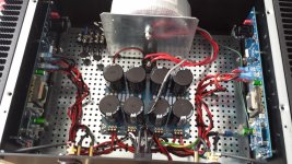
So any constructive incite or previous experience that was out of the norm would be greatly appreciated. I will post pics not sure best but have taken lots as I just spent a day dismantle and going over ever solder joint wire connection etc. I have even removed trans as far as wires permit put a tin over top and same hum.
Any assistance appreciated It has me baffled .Thanks.😕
My issue is a familiar one and it's the hum issue i am having. I have read everyone else remedies and I have tried all with no avail. I do not posses an oscilloscope only a DMM . I am starting to wonder if I have an issue unrelated to a simple wire routing/ground loop problem. ie. transformer,filter caps ,resistor noise,etc. I don't know .
So any constructive incite or previous experience that was out of the norm would be greatly appreciated. I will post pics not sure best but have taken lots as I just spent a day dismantle and going over ever solder joint wire connection etc. I have even removed trans as far as wires permit put a tin over top and same hum.
Any assistance appreciated It has me baffled .Thanks.😕
Attachments
Last edited:
More pics...
More pics have others too.🙂
More pics have others too.🙂
Attachments
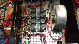
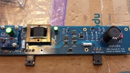


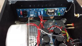
Edcor is unshielded which may pickup hum from trafo/wires?
Power lines to amp and speaker wires are twisted together so ripple on supply may transfer to speaker wires?
You use only one bridge and centertap on trafo as ground? …..this could introduce more ripple than using double-bridged PSU?
Power lines to amp and speaker wires are twisted together so ripple on supply may transfer to speaker wires?
You use only one bridge and centertap on trafo as ground? …..this could introduce more ripple than using double-bridged PSU?
If you have the PSU board ground jumpers connected at both ends of the board, remove one set and only jump them at one end, not both (ground loop induced hum).
Edcor is unshielded which may pickup hum from trafo/wires?
Power lines to amp and speaker wires are twisted together so ripple on supply may transfer to speaker wires?
You use only one bridge and centertap on trafo as ground? …..this could introduce more ripple than using double-bridged PSU?
I goof on ordering trans and got a center tap I was instructed to wire as in picture ,maybe incorrect but I have connected it at both ends of psu boards no diff. Also have made sure wires not as you stated. Yes edcor isnt shielded but i moved trans about 24 inch away and put steel can over it ,no change.Thanks
Last edited:
If you have the PSU board ground jumpers connected at both ends of the board, remove one set and only jump them at one end, not both (ground loop induced hum).
I read that one and cut at the output end ,no difference I soldered back together. thanks


With a centre tapped transformer the ground of both sides of the board need to be connected together, and you have done that.
However, you are taking the ground off the power supply board at multiple locations. See recommendation by diyAudio member Bonsai:
http://hifisonix.com/wordpress/wp-content/uploads/2019/02/Ground-Loops.pdf
See pages 58,59,and 60.
With your board, use a thick gauge wire and connect to ground connectors on both sides of the board output. Then take all of your ground wires from the centre point of the wire. In other word, make a "T" from wire.
There is also other information and tips in the article.
I did try to rap my head around that long article and I do understand the T for all grounds, but I have built according to the guides here on diyaudio and all before me , this is puzzling why more people haven't the same issue. Is there a possibility the transformer is to blame?Thanks for your info.With a centre tapped transformer the ground of both sides of the board need to be connected together, and you have done that.
However, you are taking the ground off the power supply board at multiple locations. See recommendation by diyAudio member Bonsai:
http://hifisonix.com/wordpress/wp-content/uploads/2019/02/Ground-Loops.pdf
See pages 58,59,and 60.
With your board, use a thick gauge wire and connect to ground connectors on both sides of the board output. Then take all of your ground wires from the centre point of the wire. In other word, make a "T" from wire.
There is also other information and tips in the article.
Will try the T grounding ...
Put wires between L/R input grounds and between L/R speaker grounds.
Tried that nothing changed.thanks
Does it make a change if you have only one channel powered?
Maybe try both. Left only and then right only.
Maybe try both. Left only and then right only.
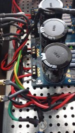
Should my center tap be at the in or out point? It is split to two connectors since i first tried to hook to two rectifiers unknowing at time it can't be wired that way. I am only using one of those connectors. picture of present connections.
The board grounds should be tied together at both ends. The ground "T" would be at the output end.
Does it make a change if you have only one channel powered?
Maybe try both. Left only and then right only.
I tried that each channel noise is same.
The board grounds should be tied together at both ends. The ground "T" would be at the output end.
So that I have right,I think. I have tried either end,and cut then reattached the out end since no change. Isn't all the grounds for the channels coming together in that T zone at present or Am I missing something ?
Can you hear if hum is 60 or 120 Hz ?
If it is 60 Hz it may be magnetic field from power trafo to Edcor?
If it is 60 Hz it may be magnetic field from power trafo to Edcor?
Pretty sure its 60hz ,how far away would the transformer need to be to eliminate that? I will do it to rule that out or confirm.
So that I have right,I think. I have tried either end,and cut then reattached the out end since no change. Isn't all the grounds for the channels coming together in that T zone at present or Am I missing something ?
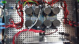
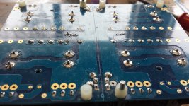
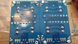
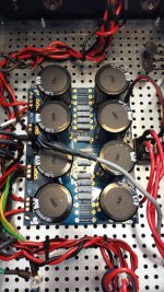
Looking at your pictures it appears to me that you have multiple ground wires connecting at the connection block at both positive and negative sides of the board. The idea of the "T" is to have all these wires connecting to one point at the "stem" of the "T", not at multiple points as it appears to me from looking at your pictures.
Have you tried rotating your transformer?
Looking at your pictures again, it looks like you have five wires connected to the ground connection blocks. If your speaker grounds are coming off the amplifier board, then you only need three ground wires - one for connection to chassis through the CL60, one for left channel, and one for right channel. Twist your V+,V-, and Gnd wires together for each channel. These three ground wires connect to the stem of the "T". The CL60 connection to chassis should be at the same location as the chassis/power line safety ground.
Last edited:
- Home
- Amplifiers
- Pass Labs
- First Watt M2x issue.