I connected as per the guide ,which I see a lot have only used three wires to amp boards . I have tried that too and no difference . Also rotated transformer . Its frustrating me and i usually can figure anything out.😕
Attachments
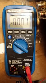
If you use a DMM set to mV/AC how much AC is at speaker out at "idle" (no music….like grounded input)?
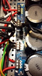
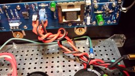
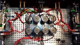
The white wire that seems to go between the two RCA in.....probably connecting the two RCA signal gnd's?
I would not do that…...
I would not do that…...
If you use a DMM set to mV/AC how much AC is at speaker out at "idle" (no music….like grounded input)?
B channel is the higher one.
Attachments
The white wire that seems to go between the two RCA in.....probably connecting the two RCA signal gnd's?
I would not do that…...
That was from a previous suggestion, didn't do anything,removed.
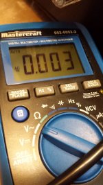
So approx. 1 and 3 mV …...which is way too much. I like to be down to approx. 100 uV which ensures a silent setup with my speakers.
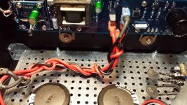
Can we learn something about which channel is B.....is B the channel where power wires from power trafo comes close to amp?
Can we learn something about which channel is B.....is B the channel where power wires from power trafo comes close to amp?
You still have speaker output wires twisted together with DC power wires (which has some ripple…...that could transfer capacitive)?
What is AC measured at DC......how much ripple?
What is AC measured at DC......how much ripple?
From the auto range its .001 of a volt switch to any other non auto range says 0v. No that's the opposite board to the side DC wires. I will untwist from speaker wires.
You still have speaker output wires twisted together with DC power wires (which has some ripple…...that could transfer capacitive)?
What is AC measured at DC......how much ripple?
Not sure what you mean ripple, only have a DMM.
Did you try the "T" connection?
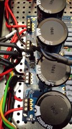
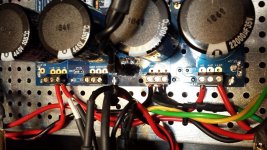
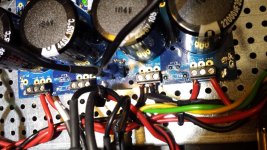
I still see the separate ground wires going to the two ground connection blocks. Plus I see two wires connected to the PS board ground between the two output connection blocks. Where do those wires go?
I still see the separate ground wires going to the two ground connection blocks. Plus I see two wires connected to the PS board ground between the two output connection blocks. Where do those wires go?
Not sure what you mean ripple, only have a DMM.
Ripple is how much AC you have on your DC (+22V and -22V). Measure same way as you measured AC at speaker out.
But I think you should try to isolate the speaker wires from PCB to speaker binding posts from the DC power wires. Maybe pull speaker wires from PCB and then measure AC direct on PCB to check if you still have 1 or 3 mV noise.
Did you try the "T" connection?
I still see the separate ground wires going to the two ground connection blocks. Plus I see two wires connected to the PS board ground between the two output connection blocks. Where do those wires go?
I may have sent wrong pic ,here is what i have now one grd block is empty. The two grounds going to amp one from psu other is speaker grd.Not sure if this is T ground or I need something else to implement ,hunk of wire?
Attachments
I may have sent wrong pic ,here is what i have now one grd block is empty. The two grounds going to amp one from psu other is speaker grd.Not sure if this is T ground or I need something else to implement ,hunk of wire?
That is not a "T". The is more of a "L". For a "T", connect the two Ground connection blocks with a heavy piece of bare wire, and connect your Ground wires to the midpoint of the bare wire between the connection blocks.
But as I mentioned in my previous post, I see two wires connected to the quick connector tab between the two ground connectors. Where do those wires go? That may be your problem.
Edit:
You said, "The two grounds going to amp one from psu other is speaker grd." I don't understand.
Last edited:
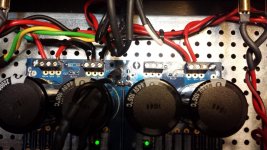
The transformer centre tap should be connected to the input end of ground. The speaker ground should be connected to the output end of ground. The output end is the "clean" end so the transformer, which is AC, should not be connected to it.
If you read the Hifisonix article, he stresses that the ground should originate from the power supply at one point, and also that one point should be half-way between the negative and positive ground. You have ground connections at multiple locations and also the connector block you are using is not half-way between the negative and positive grounds.
Please look at that article again.
PS: With this quick flurry of posts when both of us are posting at the same time, now I see that your transformer centre tap is at the input end of ground, so that is correct.
Please look at that article again.
PS: With this quick flurry of posts when both of us are posting at the same time, now I see that your transformer centre tap is at the input end of ground, so that is correct.
Last edited:
- Home
- Amplifiers
- Pass Labs
- First Watt M2x issue.