I think your load model is wonky. It's only defined up to 20kHz. If you extend thel load data out into the MHz region, things look a lot different, but still have issues. I think a varisttor may not be the best way to approach modelling a loudspeaker load.OK. Here is my F7 sim. In the attachement you can find the complete sim as zip.
Have fun.🙂
I noticed the trimmers Nelson used look non-standard so they might sound nicer.
As I recall, he had them custom made for FW. You can do that when ordering a lot at once.

Hi all, On a different topic . . .
I'm just about to order a PCB & Parts for an F7 build and would appreciate advice for these two parts.
i ) What resistor Brands / Types have you got the best results with for the R sense. i.e. Which ones have you used that sound best ?
So far I am thinking Chassis Mount Non-Inductive Wire Wound or Surface Mount.
ii ) What Electrolytic Brands / Types would you recommend for the PSU Capacitor Banks ?
Many thanks
Last edited:
i) Caddock MP30
ii) Almost anything will do. I doubt it makes much difference in the real world, as long as it isn't a cheap generic or store brand.
ii) Almost anything will do. I doubt it makes much difference in the real world, as long as it isn't a cheap generic or store brand.
Why should not a varistor be suitable for simulating an impedance?I think your load model is wonky. It's only defined up to 20kHz. If you extend thel load data out into the MHz region, things look a lot different, but still have issues. I think a varisttor may not be the best way to approach modelling a loudspeaker load.
The matrix Z(f) is clearly defined with f, R and phase.
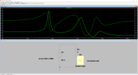
I mapped the crossover with the chassis in LTspice and extended the SPK model to 200 kHz (pic #6).
Unfortunately LTspice runs in limbo when I extend the SPK model to 1 MHz.
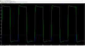
The test result with my F7 sim and 10 kHz square wave looks better now (pic #7).
But I like it even less than the previous model up to 20 kHz.
Conclusion: my SPK does not match my F7 clone or my F7 clone does not match the SPK.
The sound is not what I like and I can't imagine that it can be because of the trims.😎
Attachments


I would suggest that removing ( cermet ) trimmers from the signal path is one of the most significant single mods one could ever make but of course there might be more than one reason why you don't like the sound of the amp.Why should not a varistor be suitable for simulating an impedance?
The matrix Z(f) is clearly defined with f, R and phase.
I mapped the crossover with the chassis in LTspice and extended the SPK model to 200 kHz (pic #6).
Unfortunately LTspice runs in limbo when I extend the SPK model to 1 MHz.
The test result with my F7 sim and 10 kHz square wave looks better now (pic #7).
But I like it even less than the previous model up to 20 kHz.
Conclusion: my SPK does not match my F7 clone or my F7 clone does not match the SPK.
The sound is not what I like and I can't imagine that it can be because of the trims.😎
Check out the attached white paper too see why cermet trimmers are bad news for audio.
Attachments
Agreed - there was a time when I used Caddock MK132s in critical positions but later found that I preferred the sound the good metal films.Yes, cermet pots are thick film resistors too.
The Bourns 3329 cermet pots are sealed, and very good for stable adjustments.
I've used them for many years.
I've used them for many years.
I just think you will get a more realistic result for your square waves if you use a loudspeaker model built with reactive components, like this one.Why should not a varistor be suitable for simulating an impedance?
The matrix Z(f) is clearly defined with f, R and phase.
I mapped the crossover with the chassis in LTspice and extended the SPK model to 200 kHz (pic #6).
Unfortunately LTspice runs in limbo when I extend the SPK model to 1 MHz.
The test result with my F7 sim and 10 kHz square wave looks better now (pic #7).
But I like it even less than the previous model up to 20 kHz.
Conclusion: my SPK does not match my F7 clone or my F7 clone does not match the SPK.
The sound is not what I like and I can't imagine that it can be because of the trims.😎
I also doubt the trimpots are the issue.
Attachments
Thank you for the model. The test results are attached.
Impedance curve for kantor (pic #8)
F7 sim response with kantor (pic #9). It looks a lot nicer.
My model captures all reactive parts of a real speaker B&W 804 with bass reflex principle
and agrees with results already published here:
https://www.stereophile.com/content/bowers-amp-wilkins-804-diamond-loudspeaker-measurements
The model is structured as follows:
.subckt B&W804_200kHz 1 2
B1 1 2 V=I(B1) MAG FREQ=
+10.071, 4.972, 29.086
+10.437, 5.084, 30.183
+10.803, 5.140, 31.170
.
.
.
+200000.0, 24.919, 79.000
.ends B&W804_200kHz
Each row contains a triplet: frequency, resistance and phase angle
This data depict a measured impedance curve in reality and is one possible electrical
mapping of a speaker with its crossover and chassis' and contains all reactances.
The two models describe the same principle. The only difference is the notation used.
Sure, in my model the frequency ends at 200 kHz (LTspice crashes with data over 200 kHz).
But should it make a such big difference when testing at 10 kHz?
Attachments
To the people expressing "views" about the impact of cermet trimmers on Sound Quality I would ask one question:
How many times have you done A/B tests comparing cermet trimmers with a good quality film resistor ?
I do this test every time I build a new amp because after the initial setup & test with trimmers, I then remove the trimmers from their sockets, measure them and then replace with fixed value film resistors and the difference is audible every time.
I would guess that if commercial metal oxide were being used in all other positions this difference might be hard to notice.
But if you are chasing good sound quality, I suggest you avoid most types of commercial metal oxide resistors in general and cermet trimmers in particular.
Some more specialised Metal Oxide resistors can sound better but I have yet to find one that matches a good quality metal film.
Just for clarification Metal Oxide, Thick Film, Cermet Trimmers & NTC Thermistors all are varieties of Metal Oxide.
Nelson says that the F7 current sense resistor should not be too large.
Do we think that 1 ohm - as in this circuit would be OK ?
Many thanks

Do we think that 1 ohm - as in this circuit would be OK ?
Many thanks
Last edited:
The sense resistor choice is a balance with input network, feedback network, load and desired DF.
Generally we want the sense resistor low.
Generally we want the sense resistor low.
Thanks Nelson,
In the diagram, the values are set to give a damping factor of about 5 with no positive FB and a damping factor about 56 with the positive FB.
Am just hoping that the 1 ohm sense resistor will be OK in all other respects - is 1 ohm low enough ?
thanks
In the diagram, the values are set to give a damping factor of about 5 with no positive FB and a damping factor about 56 with the positive FB.
Am just hoping that the 1 ohm sense resistor will be OK in all other respects - is 1 ohm low enough ?
thanks
I'm just curious what the actual downside is of having a 1 ohm current sense resistor with an 8 ohm load apart from the fact that you would need marginally more voltage developed at the O/P to achieve the same power in the load.
I guess it could be a dynamics thing - particularly with a 4 ohm speaker - that makes some kind of sense. The dynamic "boost", particularly in speakers with tricky impedance dips, would be proportionality less, the greater the R sense was.
I guess it could be a dynamics thing - particularly with a 4 ohm speaker - that makes some kind of sense. The dynamic "boost", particularly in speakers with tricky impedance dips, would be proportionality less, the greater the R sense was.
efficiency, as first
in other words, least resistance you can get with, while having enough modulation to feed back
in other words, least resistance you can get with, while having enough modulation to feed back
- Home
- Amplifiers
- Pass Labs
- First Watt F7 review