SO more questions as I am ordering parts. Are all those 3 watt Resistors wirewound?
C5 should be a polarized capacitor?
Wirewound resistors can be used but metal film would probably be better.
C5 is a film cap preferable polypropylene but I have been know to use polyester to save money.
Wdecho picodunb replied some of them are Panasonic metal oxide resistors .
Also are you sure about the Cap? I remember seeing a board picture but it was a polarized cap I believe?
Also are you sure about the Cap? I remember seeing a board picture but it was a polarized cap I believe?
Wdecho picodunb replied some of them are Panasonic metal oxide resistors .
Also are you sure about the Cap? I remember seeing a board picture but it was a polarized cap I believe?
Metal oxide is a good choice as well. Judging by the schematic posted the C5 cap is not polarized. No + with the cap means non polarized. As far as the resistors as long as the value and power rating is correct there should be no difference in the sound between the type you choose. Cost usually determines what I use and that is determined by my bank account when I order. My funds also determine whether I buy 1% or 5% as well.
Last edited:
25V should be adequate but the price difference between a 25V and 35V is not that much. I usually buy 35V for this type of circuit. Be sure you use a good polypropylene for C2. I would up the farad to 10uf myself. It should only be better with 10uf vs 1uf.
The supply shows as 24Vdc. That should allow a 25V rated capacitor to be used.
How much could the supply voltage vary? Could it go above 25Vdc?
How much could the supply voltage vary? Could it go above 25Vdc?
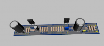
Not above 18V. Andrew size is the issue. I am making a PCB. I am not so happy with what is available in market for PCB as it places both FETs really close to each other.
My mistake C4 is only 1000uf I was looking for a 15000uf one.
My mistake C4 is only 1000uf I was looking for a 15000uf one.
micro femto.
Another Member kindly pointed out this nonsense a couple of days ago.
F = Farad
f = femto
The sch shows 1000uF and 15000uF (=15mF), which are you proposing to change?
Another Member kindly pointed out this nonsense a couple of days ago.
F = Farad
f = femto
The sch shows 1000uF and 15000uF (=15mF), which are you proposing to change?
No change Andrew. In older F2 schematic C4 and C6 both were 15000uF.
I see in the new F2J schematic C4 has been changed to 1000uF.
That is why the confusion happened.
To fit a long PCB into 4U chassis I needed one cap to be small.
I see in the new F2J schematic C4 has been changed to 1000uF.
That is why the confusion happened.
To fit a long PCB into 4U chassis I needed one cap to be small.
I used this calculator zen.
http://www.4pcb.com/trace-width-calculator.html
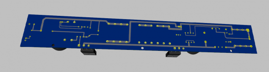
I guess the maximum current in the traces between 8-10Ampere.If it is 8 Amp then this traces are enough 3mm in thickness. But if it is 10amp may be not.
http://www.4pcb.com/trace-width-calculator.html
I guess the maximum current in the traces between 8-10Ampere.If it is 8 Amp then this traces are enough 3mm in thickness. But if it is 10amp may be not.
Last edited:
well , if you're making calculator , their advices are OK
if you're going to make state of the art amp ........
if you're going to make state of the art amp ........
drain/sources traces ........ I wouldn't go lesser than 5mm , routing both planes (top and bottom)
that's at least how I'm doing these
that's at least how I'm doing these
- Status
- Not open for further replies.
- Home
- Amplifiers
- Pass Labs
- First watt F2j with SJDP120R085