Ok, what I meant was they should track with minimum phase difference between them (close to 0). I think this is the general meaning of phase tracking.
Yes I understood that.Ok, what I meant was they should track with minimum phase difference between them (close to 0). I think this is the general meaning of phase tracking.
That's why I publish both.
BW filter sum flat at -3db with phase 90degrees separated between both.
LR filter sum flat at -6db with 0degrees separated between both.
BW seems to have flatter DI.
At least that's what I understood of it, hence my post so ppl can give some comment/suggestions/recommendations/....
Ok, my suggestion was waveguided tweeter, I think that should get you smoother directivity and good phase tracking
Yes ,it would improve things. Just a bit worried about the woodwork. There is an oval shape waveguide for this tweeter. But making the cut out is a bit more demanding.Ok, my suggestion was waveguided tweeter, I think that should get you smoother directivity and good phase tracking
I wouldn't agree with that.IMHO phase tracking between drivers is good for depth in the sound stage, I would not like to compromise on that.
Good, we can agree to disagree 🙂
Good to get different opinions, and maybe MrHifiTunes will have the chance to test and make up his own mind.
I think an active XO setup is a good way to experiment with stuff like that and listen to what you hear and don't hear 'on the fly'.
Good to get different opinions, and maybe MrHifiTunes will have the chance to test and make up his own mind.
I think an active XO setup is a good way to experiment with stuff like that and listen to what you hear and don't hear 'on the fly'.
Can you give a bit more information? I'm trying to learn and understand things better.I wouldn't agree with that.
What's most important to get 3D soundstage?
I was just saying that phase doesn't have to be the same (but don't think I am saying you can do just anything with it 😉 )
To answer your question on most important for imaging (all else being ok), your secondary sources.. ie diffractions, and controlling your reflections.
To answer your question on most important for imaging (all else being ok), your secondary sources.. ie diffractions, and controlling your reflections.
Thanks, So smooth off axis and DI together with paying some attention to the baffle layout and shape will contribute to good imaging.I was just saying that phase doesn't have to be the same (but don't think I am saying you can do just anything with it 😉
To answer your question on most important for imaging (all else being ok), your secondary sources.. ie diffractions, and controlling your reflections.
I end up with rather flat curves in my simulation iso linear sloped down/up. 🤔
@MrHifiTunes: If you want to know any specific details regarding the wide baffle 2 way speaker, if you are facebook, you can ask the designer Scott Hinson on this facebook group:
https://www.facebook.com/DIYRM/He is also a moderator in this group:
https://www.facebook.com/groups/DIYLoudspeakerProjecPad/?ref=share
PS: Sorry, I really dont know why the facebook group links are shown in some language unknown to me instead of english.
https://www.facebook.com/DIYRM/He is also a moderator in this group:
https://www.facebook.com/groups/DIYLoudspeakerProjecPad/?ref=share
PS: Sorry, I really dont know why the facebook group links are shown in some language unknown to me instead of english.
Not exactly. I'm talking more about acoustic design than crossover work.So smooth off axis and DI together with paying some attention to the baffle layout and shape will contribute to good imaging.
You should be using Vituixcad after this, these things are not what it was intended to do. Baffle shape rearranges diffraction but I'm talking about reducing diffraction (this is not something you can see by looking at response). DI is a blunt instrument which you need to consider from an earlier point in the design.
Without this all you are doing is making the best of an uncertain situation.
Last edited:
Thanks, I send him a message.@MrHifiTunes: If you want to know any specific details regarding the wide baffle 2 way speaker, if you are facebook, you can ask the designer Scott Hinson on this facebook group:
https://www.facebook.com/DIYRM/He is also a moderator in this group:
https://www.facebook.com/groups/DIYLoudspeakerProjecPad/?ref=share
PS: Sorry, I really dont know why the facebook group links are shown in some language unknown to me instead of english.
Are Chinese hacking us? LOL 😎
Its been a while since I posted here. Process is slower then I would liked.
So far drivers are delivered and I made a tractrix brace template.
With router copyring will add 6mm in each direction.
The drivers are really looking nice and of high construction quality. 👍
SB26ADC
SB12MNRX2
SB23NRX45-8
The faceplace of the tweeter looks a bit blacker....maybe because it has a smoother surface.
Behind the woofer I will keep 1cm internal open space. Is this sufficient? there is a big hole in the centre of the driver. I guess it will push some air out.
Probably will go for a wave guide on the tweeter.
Dont know yet how to make the curved sidepanels. 🤔
But first holidays...gives me some time to think about things.
Did some reseach on curving wood.
Seems with a tappered CNC ball nose bit you can make cuts so that the opening gap is a bear minimum compared to using the tablesaw.
Did anyone try this methode? Doing it with a router seems a hell of a job for panels more then 1m long. 😕 But once its done you may have the benefit from it.

Seems with a tappered CNC ball nose bit you can make cuts so that the opening gap is a bear minimum compared to using the tablesaw.
Did anyone try this methode? Doing it with a router seems a hell of a job for panels more then 1m long. 😕 But once its done you may have the benefit from it.
Looks like an even more time-consuming way of doing it 🙂
Thinking about it afterwards, I think I would glue a thin sheet of aluminum to the insides after cutting the slits and bending the panel to shape. I have a feeling that would stabilize it really well, and maybe even give some of that constrained layer damping effect. Would probably be pretty easy to just slap it on with a lot of glue after the panels have been bent and glued to the 'shaped braces'.
Doing the tight radiuses I think you will have to do something with the router/sanding etc, you will not be able to bend the MDF(?) too much without them cracking and falling apart.
The cuts have to go almost through (1-2mm thickness), or the MDF will crack when you bend it. Wetting it might help a bit though.
I think 1cm should be enough for the pole vent, but I would leave more margin. Maybe you find the rear panel is resonant and want to glue a floor tile on it or something..
Absolutely. Only advantage I see is that I only need to buy a routerbit (10 euro). I dont have a saw with guiderail which would be more expensive to buy (150 euro minimum).Looks like an even more time-consuming way of doing it 🙂
I saw some video's they bend it slowly to release some stretch from the wood. Wetting and warming (steam iron) it helps too. Will try first on a scrap board because it is a small radius.Thinking about it afterwards, I think I would glue a thin sheet of aluminum to the insides after cutting the slits and bending the panel to shape. I have a feeling that would stabilize it really well, and maybe even give some of that constrained layer damping effect. Would probably be pretty easy to just slap it on with a lot of glue after the panels have been bent and glued to the 'shaped braces'.
Doing the tight radiuses I think you will have to do something with the router/sanding etc, you will not be able to bend the MDF(?) too much without them cracking and falling apart.
The cuts have to go almost through (1-2mm thickness), or the MDF will crack when you bend it. Wetting it might help a bit though.
I can make a cut 1cm deep behind the driver.I think 1cm should be enough for the pole vent, but I would leave more margin. Maybe you find the rear panel is resonant and want to glue a floor tile on it or something..
Still not sure how to make a stand for the speaker. I want to tilt it around 5degrees. Maybe I put some long square metal rod in the back make it more stable. This can also be used to put the cables. I plan to make the crossover in the base of the speaker in a separated compartment (if all the componets fit 😎 ) I dont think the speaker will be finished next month or so....😎 luckily I still have some speakers to listen to and enjoy my music.
I only used a straight piece of MDF to guide the saw when I cut the slits, went reasonably well even if the saw was a POS. Everything else was cut on a professional saw.
I have three legs, two at the front, and one 2x4 sticking out maybe 15cm in the back at 45deg angle. They are not supposed to be against the wall anyway, if so, they could be hanging on the wall 🙂 The rear 'leg' has a threaded foot, so the angle can be adjusted. They are very stable like that, I would not like them to fall over while cleaning or people leaning on them or something.. The XO was tuned for 0deg, and that is how they sound best (even if vertical off axis is not critical).
I have three legs, two at the front, and one 2x4 sticking out maybe 15cm in the back at 45deg angle. They are not supposed to be against the wall anyway, if so, they could be hanging on the wall 🙂 The rear 'leg' has a threaded foot, so the angle can be adjusted. They are very stable like that, I would not like them to fall over while cleaning or people leaning on them or something.. The XO was tuned for 0deg, and that is how they sound best (even if vertical off axis is not critical).
Been a while since I had posted new developments. The project is going slow though.(due to health issues)
I made a test box (square box) and made some measurements as a first startpoint.
The final cabinets are almost finished.
The bending and curved side panels were more difficult then I thought, but they came out ok.
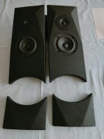
For the front baffle I made a separate baffle for the tweeter and mid driver covered with some fake leather.
The woofer will have an extra support ring to make them sticking out a bit more. (Allow them a bit more breathing space on the back)
Will make some more pictures later.
I made a test box (square box) and made some measurements as a first startpoint.
The final cabinets are almost finished.
The bending and curved side panels were more difficult then I thought, but they came out ok.
For the front baffle I made a separate baffle for the tweeter and mid driver covered with some fake leather.
The woofer will have an extra support ring to make them sticking out a bit more. (Allow them a bit more breathing space on the back)
Will make some more pictures later.
Attachments

I did a similar setup first, with a separate baffle, but after measuring FR I removed it.. Drivers mounted flush with the baffle measured better.
- Home
- Loudspeakers
- Multi-Way
- First project : Troels PMS with SBacoustic drivers ; advice and help most welcome