Yeah, sorry I could not refrain. Besides this is DIYA and we are allowed (and supposed) to try every PS-circuit-cable-connector...etc, we imagine to suit our taste or experiment. (just see my speaker connection, if you can, from the bad pics)
I plan to build a conventional linear supply powered FO (50mF per rail) just to convince me which approach is better, as I already had the parts.
Anyway, when we are building 10 different amps, we seek cheaper and more efficient power alternatives. 😱
Cheers,
M.
Looking foreward to your conclusion Maxlorenz
CapBank for First One M upgrade
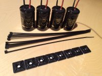
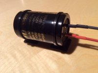
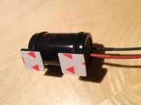
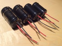
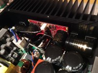
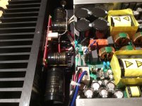
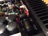
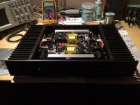
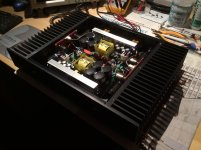
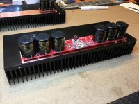
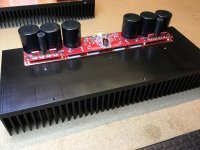
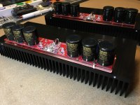
Here's photo instructions how to upgrade existing First One amplifier with capbanks, in simplest way. 😎
Here's photo instructions how to upgrade existing First One amplifier with capbanks, in simplest way. 😎
Attachments
-
 IMG_0698.JPG565.2 KB · Views: 838
 -
 IMG_0706.JPG460.4 KB · Views: 770
 -
 IMG_0704.JPG457.3 KB · Views: 751
 -
 IMG_0709.JPG529.3 KB · Views: 731
 -
 IMG_0710.JPG679.1 KB · Views: 742
 -
 IMG_0711.JPG777.4 KB · Views: 412
 -
 IMG_0712.JPG741.4 KB · Views: 413
 -
 IMG_0713.JPG633.6 KB · Views: 1,032
 -
 IMG_0714.JPG582.6 KB · Views: 322
 -
 IMG_0715.JPG611.3 KB · Views: 318
Nice, Thanks. I thought smps did not like too much capacitance at the ouput?Here's photo instructions how to upgrade existing First One amplifier with capbanks, in simplest way. ��
Generally SMPS's output current limiter prevents start-up sequence at short circuit or high output capacitance, since charging current easily exceeds few tens of amperes. SMPS1200A400 power-on output characteristic is pure square wave function, so it looks that overcurrent protection has inherent time delay allowing output current to settle to normal level within one second, thus enabling high output capacitance. That makes Hypex SMPS even more suitable for audio use compared to other producers, preferred choice for audio power amplifier.
I did something similar but instead of sticking the new cap to the hot heat sink I hot glued the new cap to the existing cap and secure with cable tie. And soldered the new cap to the existing cap pcb solder pad under the pcb.
Cheers
Ck
Cheers
Ck
Attachments
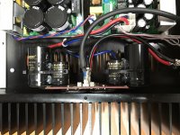
That's OK Ck, even better solution. 
But for me opening the hood, not removing anything, it was a simple & quick fix. 🙂
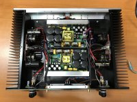
CapBank modules in pics below is probably most elegant variant of them all. 😉
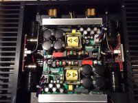
I see WBT and Hypex too. How are you pleased with the sound? Other parts of the system?
But for me opening the hood, not removing anything, it was a simple & quick fix. 🙂
CapBank modules in pics below is probably most elegant variant of them all. 😉
I see WBT and Hypex too. How are you pleased with the sound? Other parts of the system?
Attachments

I was using Teddy Prado 100w mono before this amp driving a pair of Genesis IM8300. Never hear the speaker sing so well before for the past 10 yrs.
Nothing really problem except the amp need few seconds to discharge after power down with some funny sound from the speaker and also after adding cap I encounter 2-3 times one channel not powering up when turning on the amp. I suspect the startup current too high and cause one of the psu shutting down. Randomly happen on either side. But a power down and up always works. Maybe my fault of shutting down too fast when changing cables or preamp. Not sure. Just know it's sounds great.
My friend came my office heard my amp ask me to diy one for him also. Another friend studying to make one too. I have reserved 2 FO M module previously please add 2 more FO M to my order. Also waiting for your dual mono chassis and FO L module also. Great job.
Cheers
Ck

Not to pollute this thread but here's the finished ATS-4 speakers. My friend Royber and I both made an identical pair.
Troels Gravesen ATS-4!
Do
Troels Gravesen ATS-4!
Do
Do,
What fantastic DIY! My hats off to you, you are my DIY hero!
LC,
Are those cap module boards available for purchase with your FO boards?
Best,
Anand.
What fantastic DIY! My hats off to you, you are my DIY hero!
LC,
Are those cap module boards available for purchase with your FO boards?
Best,
Anand.
Here's photo instructions how to upgrade existing First One amplifier with capbanks, in simplest way. 😎
What a good solution!
Is this also possible with the V1.3? (not quite ready to build a V1.4)
R.
Here's photo instructions how to upgrade existing First One amplifier with capbanks, in simplest way. 😎
Mounting the electrolytic caps onto the heatsink does not seem ideal to me because the heat will affect the life time of the caps. And how long will the self adhesive thingy stick to the heatsink?
Measured 48 °C temp in closed chassis, all Mundorf caps on PCB and these extra added at exactly the same temperature. Also new ones are well isolated via plastic holder and they have specified life time of 3000 hours at 125 °C or 16000 hours at 85 °C, no worries here.Mounting the electrolytic caps onto the heatsink does not seem ideal to me because the heat will affect the life time of the caps. And how long will the self adhesive thingy stick to the heatsink?
Producer of self adhesive holders specified them for 60 °C, we have to give opportunity to new technology and materials. Regular products will of course have Cap Bank PCB on each side of First One module. 😎
What a good solution!
Is this also possible with the V1.3? (not quite ready to build a V1.4)
R.
Yes of course, it mainly depends on power supply's output current capability, not power amp itself. 😉
Yes of course, it mainly depends on power supply's output current capability, not power amp itself. 😉
That's good news, I am using the Hypex 1200A400. Could you tell me where I can hook up the extra caps on the V1.3?
R.
That's good news, I am using the Hypex 1200A400. Could you tell me where I can hook up the extra caps on the V1.3?
R.
And then it became very silent, I don't want to be impatient but I really want to know!... OK I am a bit impatient since I the correct caps laying around..haha.
R.
And then it became very silent, I don't want to be impatient but I really want to know!... OK I am a bit impatient since I the correct caps laying around..haha.
R.
It's not that hard... Between SMPS and amp. V+ to positive side of cap other side to ground. V- to negative side of cap other side to ground. I am sure you can find some examples somewhere on the internet
That's good news, I am using the Hypex 1200A400. Could you tell me where I can hook up the extra caps on the V1.3?
R.
All versions are exactly the same when it comes to adding caps. You are just trying to put the new capacitors in parallel with the existing ones like this schematic.
If you take your modules off the heatsink you can just solder wires to the same points that the original Mundorf caps are soldered to. Copy the wiring scheme so that you make sure the negative and positive sides of the capacitors are connected the same as the original capacitors.
If you don't want to remove the boards from the heatsink then you will need to follow the pictures LC showed where you solder the wires to the power supply points on the top of the board. As Mark said on V+ line capacitor positive to V+, capacitor negative to ground. On V- side capacitor positive to ground and capacitor negative to V-. The same way as the schematic above shows.

- Home
- Vendor's Bazaar
- First One - mosFET amplifier module