Thanks! I already thought that they were in parallel but the pictures from LC made me a bit confused due to the wires solders on the top of the boards.
I will get my soldering iron out today!
R.
I will get my soldering iron out today!
R.
hi lazy cat i am trying to contact you for days for two F.O 1.2's.i have sent you a couple of pm's.i don,t have your email.
CapBank modules in pics below is probably most elegant variant of them all.
With the CapBank, What is the best way to feed the power?
Are you using the FO power-in terminals or do you recommend to move the feed to the CapBank power supply terminal??
hi lazy cat i am trying to contact you for days for two F.O 1.2's.i have sent you a couple of pm's.i don,t have your email.
esl@siol.net listed on the first page 😉
With the CapBank, What is the best way to feed the power?
Are you using the FO power-in terminals or do you recommend to move the feed to the CapBank power supply terminal??
The cap boards are used inline between the power supply and amp modules. Power supply is connected to the input on the cap board and then the output is connected to the amp modules where the power supply would normally be directly connected.
And then it became very silent, I don't want to be impatient but I really want to know!... OK I am a bit impatient since I the correct caps laying around..haha.
R.
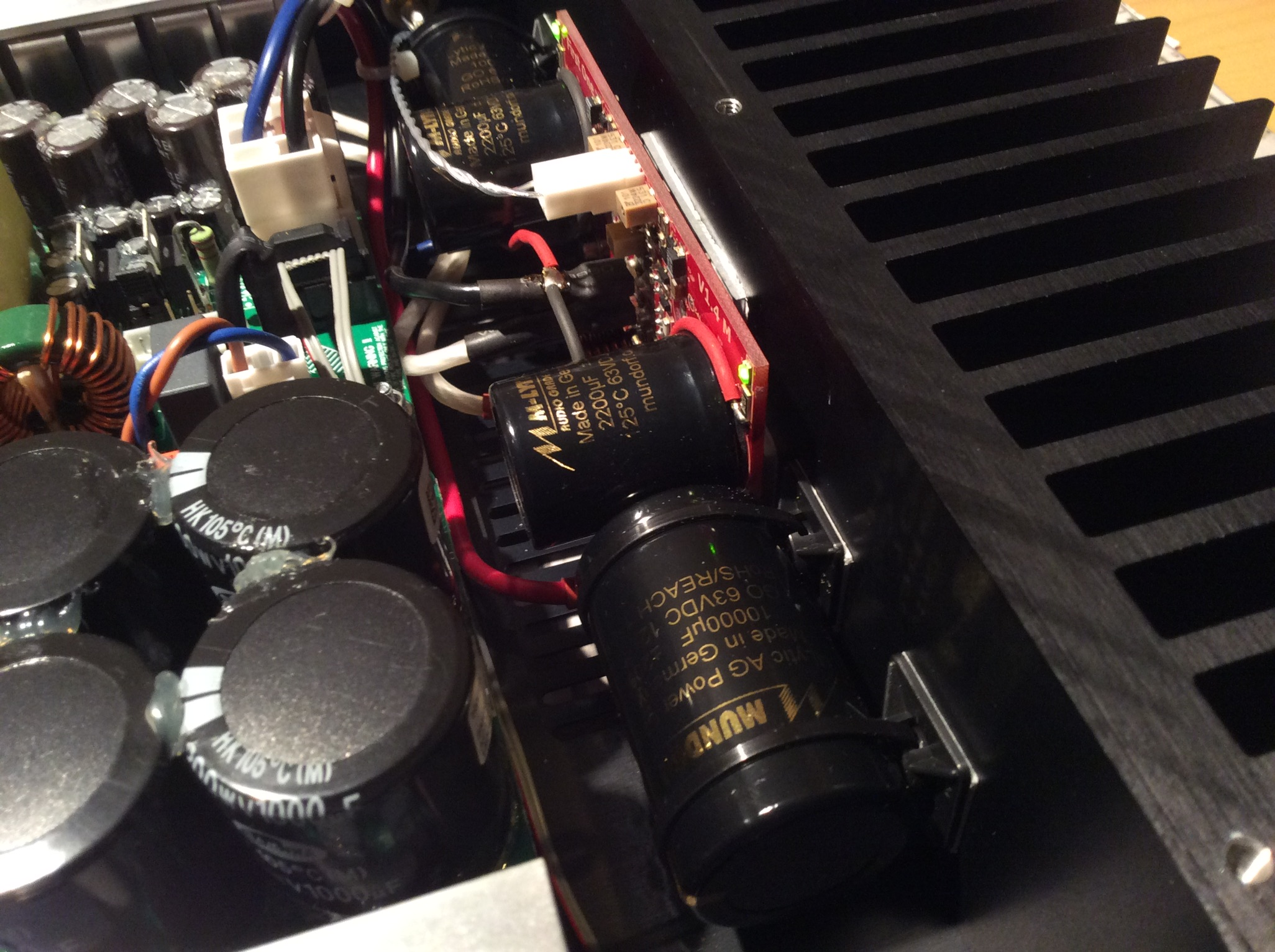
Not necessary to remove the board: positive lead to new cap then to positive board PS input connector; the same for the negative lead to extra cap; remember Hypex SMPS will have one spare ground connection if using double-mono configuration and you can return there both ground leads for star config. (as my bad photo show)
I say run to do the mod guys...you will experiment the known (and disagreeable) "why didn't I make this mod sooner" feeling. 😀
Cheers,
M.
hi lazy cat i am trying to contact you for days for two F.O 1.2's.i have sent you a couple of pm's.i don,t have your email.
I think LC is working like hell.
The cap boards are used inline between the power supply and amp modules. Power supply is connected to the input on the cap board and then the output is connected to the amp modules where the power supply would normally be directly connected.
I think that's the case with Capbank but the extra wire for the 0V in the following LC's image certainly comes directly from smps 0V.
Anyway, tomorrow I'll have some PHE169s added and report back.
So far, it's the best value for money in the whole audio chain, I've encounter.
Back, go for 1.4. I've tested both versions (1.2 and 1.4) and the later is better (even for reduced price, unless you are biamping)
Last edited:
I think that's the case with Capbank but the extra wire for the 0V in the following LC's image certainly comes directly from smps 0V.
Anyway, tomorrow I'll have some PHE169s added and report back.
So far, it's the best value for money in the whole audio chain, I've encounter.
The power supply is bipolar so when you use a bipolar pcb for the capbank it can go inline with only three wires.
When you add the caps separately then one side of each cap will need to go to ground either at the main ground tab if you don't want to remove the module or straight to the other filter caps connection on the back of the board.
Apart from the lengths of the wires there shouldn't be any effective difference.
Is it necesarry to have speaker load connected and input shorted while doing bias setting? Or can it be done with input and output open?
Thanks,
Mark.
Thanks,
Mark.
Mark, input shorted, module on heatsink, 280 mA supply current, final offset and bias calibration when temp settled. All described in user manual.
Back, go for 1.4. I've tested both versions (1.2 and 1.4) and the later is better (even for reduced price, unless you are biamping)
it,s for active 3 way but since i couldn,t find 1.2 i ordered a pair of 1.4's
they will go to the tweeters.
Hi Andrej, Is the FO 1.4 biased at 18 ma/180 mv?
And my second question, my fluke meter had a bad ampere reading (broken). In order to achieved the 280 ma supply current, I will use a resistor across the V+ supply line to get the voltage reading. What resistor value (ohms) and wattage you recommend? and what voltage reading do I get from the meter? Sorry, if this question had been asked before but no time to browse the whole thread. Trying to calibrate FO 1.4 I bought from you.
Thanks,
Fred
Hi,
I ve been recalibrating my quad FO box this week so I can suggest the folowing
you can use a 0.22ohm resistor. I ve got a rectangular 10W but you can use a 3W (P=R.I^2 you are safe) and then you will read 62milivolt (U=R.I)
LC is right, adjusting the driver stage for reading 180mv has to be done when the temp is settled, and from my experience this is an iterative process over say 1 hour (after 1 hour of heating) . also you should do the adjustement in the same condition of the final implementation of your amp in a case with the cover part as this will change the inside temp.
Finally I d say do not uderestimate this topic, if you have less than 150mv (ish) the driver stage will leave class A and will produce lots of harmonics but once you are at 180mv the driver stage is cleaner than your bathroom and you're the king. If you have to make tradeoff with the offset adjustment then this is more important than few milivolt of offset on the output.
cheers
Attachments

Last edited:
Thanks Maxidcx for your advise.
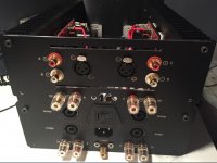
You did a good job casing your FO. Are you using it as biamp? What is the power supply your using?
Fred
You did a good job casing your FO. Are you using it as biamp? What is the power supply your using?
Fred
VAS bias is very important, as we have TO-126 on the main heatsink power dissipation is not an issue. Personally don't like DC servo and its influence to the sound so few mV DC on the output seems like a fresh breeze.LC is right, adjusting the driver stage for reading 180mv has to be done when the temp is settled, and from my experience this is an iterative process over say 1 hour (after 1 hour of heating) . also you should do the adjustement in the same condition of the final implementation of your amp in a case with the cover part as this will change the inside temp.
Finally I d say do not uderestimate this topic, if you have less than 150mv (ish) the driver stage will leave class A and will produce lots of harmonics but once you are at 180mv the driver stage is cleaner than your bathroom and you're the king. If you have to make tradeoff with the offset adjustment then this is more important than few milivolt of offset on the output.
cheers
Please consider that audio output current likes low impedance across supply rails to flow happily, as closest to power amp the better. Adding 10 mF Mundorf per rail is good enough, empty space in your chassis looks promising.
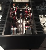
And finally, congratulations on your four channel's amplifier, it looks very professional and very seriously build. If you could write something about the sound it would make me happy and thankful.
L.C.

Hi Fredlock, thanks for your feedbackThanks Maxidcx for your advise.
You did a good job casing your FO. Are you using it as biamp? What is the power supply your using?
Fred
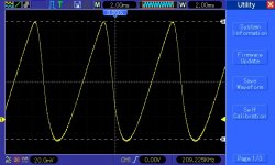
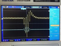
for this configuration, I m using an audiopower DPS400/S2 providing 52V on each rail for 2 modules. But a "S1" version would be more than sufficient for a single module. Here below 2 pictures from my DSO scope showing 52mv rms ripple @100hz (averaged 128) which is very good considering 2 modules load. and a burst at 100hz with FO providing 25vRMS into 3ohm load (=200w) you can see the rail droping only 3volts and recovering quickly.
I ve lowered the overall bias to 240ma per module per rail in order to get a 47°C when the case is closed. each module mounted on standard 300x40x80mm heatsink.
Hi LC!
yes I might put a bit more caps on the rail, thinking about it. But at the end what is important is the overall impedance of the PSU as seen by the FO on its faston right ? I mean we have to be more factual in this discussion about caps and I m sure it depends also on the SMPS first caps stage, the one on the 230vac side.
I will do an upgrade sooner or later and will put the same kind of Scope picture let see.
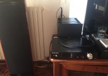
when it comes to sound , and with the gustard a20h 😉 this is just fantastic and clean. For me the FO is like a magnifier
Attachments
A question to Max Laurenz,
i have read somewhere else here that you have being experimenting with SE solid state amps. Certainly we don't all all have the privilege of having high efficiency speakers and low power SE amps, but I am really curious to know if you have compared the FO to your SE designs.
I have high efficiency speakers (based on Altec/GPA) a pair of Harbeth 30.1 and quite a few other self made speakers. I have sonny's TSSA amp, which is well regarded (and related to the FO) even among people using it with HE speakers.
I am very curious about the FO and I might give it a try, but I would really appreciate to hear about your experience anyway.
S
A question to Max Laurenz,
i have read somewhere else here that you have being experimenting with SE solid state amps. Certainly we don't all all have the privilege of having high efficiency speakers and low power SE amps, but I am really curious to know if you have compared the FO to your SE designs.
I have high efficiency speakers (based on Altec/GPA) a pair of Harbeth 30.1 and quite a few other self made speakers. I have sonny's TSSA amp, which is well regarded (and related to the FO) even among people using it with HE speakers.
I am very curious about the FO and I might give it a try, but I would really appreciate to hear about your experience anyway.
S
I don't quite understand your question...do you ask if I have compared the SIT amp to the FO connected to my high sensitivity Full Range speakers?
No I didn't. I may in the future but I don't expect nothing spectacular because of system matching...
Some thoughts:
There is magic when pairing single ended SIT amp directly to a Front and Rear horn loaded Full Range speaker, though I lose the lower end with the present bass horn, so ideally suited for chamber music and jazz. My future speaker will address that bass issue.
Vertical Power FETs (SIT) are the superior devices for audio. I have compared my SIT to my Mosfet with SK1058 and it is obvious.
IF Lazy Cat could build a high bias current feedback amp with these V-Fets, I would love to buy some. 😀
The FO paired to my big two way speakers can handle ANY music you throw at them without even noticing, and I am big fan of Wagner, Shostakovich, Prokofiev, Brukner: one gets all there is in the recording from violin solo to big orchestral tutti, so there you have.
I hope it helps,
M.
- Home
- Vendor's Bazaar
- First One - mosFET amplifier module