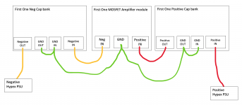
Appologies for the poor quality diagram - is this floating ground a good means of grounding the Mosfet module and it's associated cap banks? Obviously there is still a safety earth to the chassis from the IEC inlet.
I have zero experience in grounding!
I have zero experience in grounding!
Attachments
This is not enough strong switch. You have to look starting via relay or stronger push button, about 22mm and 10A, which will be capable to get first start with about 10A. And also, 5A is theory only.
Second question is, why you need such high voltage for quality power amp with 26x amplifying, so, with 2v input you need +-26V netto and +- 50V with full headroom. There are no small signal transistor in driver to cover these nut voltage without any good reason.
Second question is, why you need such high voltage for quality power amp with 26x amplifying, so, with 2v input you need +-26V netto and +- 50V with full headroom. There are no small signal transistor in driver to cover these nut voltage without any good reason.
Appologies for the poor quality diagram - is this floating ground a good means of grounding the Mosfet module and it's associated cap banks? Obviously there is still a safety earth to the chassis from the IEC inlet.
I have zero experience in grounding!
I don't understand your wiring...how the current will return from the modules to the PSU?
Best wishes,
M.
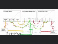
I'm not supprised this didn't make sense to people - I didn't know what I was doing, hence the question. Anyhow, I now understand a bit better. Whilst signal ground can be floating, the amplifier ground cannot because ground needs to be returned to the power supply for it to start.
Guy on Facebook gave me this better layout, which includes the ground return to the amplifier. I will also do the mandatory safetly ground to the chassis at the IEC inlet.
Guy on Facebook gave me this better layout, which includes the ground return to the amplifier. I will also do the mandatory safetly ground to the chassis at the IEC inlet.
Attachments
I apologize. I was not very extensive on the reply and was not of much help, save to increase uncertainty. The amp needs a "0V" stable reference plus the speakers return current needs a path...from my limited understanding.
Anyway, the experts want us to do our due diligence, our homework, so it is a good time for us to revisit the all-important grounding philosophy. 🙂
Best wishes of success,
M.
Anyway, the experts want us to do our due diligence, our homework, so it is a good time for us to revisit the all-important grounding philosophy. 🙂
Best wishes of success,
M.
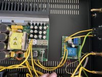
Build is progressing, one channel connected - but no sound...
Relay on the Hypex soft start clicks and powers the push button switch, but I am unsure if the Hypex SMPS is powering up. No voltage measured between First One + in and GND. I have disabled the push button switch to ensure that this wasn’t causing issue.
Any ideas?
Relay on the Hypex soft start clicks and powers the push button switch, but I am unsure if the Hypex SMPS is powering up. No voltage measured between First One + in and GND. I have disabled the push button switch to ensure that this wasn’t causing issue.
Any ideas?
Attachments
Has someone here spare M modules for sale (new or used)? I would like to upgrade my amps from v1.2. I will pay the full price of new modules + shipping to Latvia. I need 2-3 pairs total.
Build is progressing, one channel connected - but no sound...
Relay on the Hypex soft start clicks and powers the push button switch, but I am unsure if the Hypex SMPS is powering up. No voltage measured between First One + in and GND. I have disabled the push button switch to ensure that this wasn’t causing issue.
Any ideas?
My power supply was faulty - exchanges for a new Hypex and we have sound!
Push Buttons - 1NO1NC type as per below.
Anodized Aluminium Push Button with Power Symbol Blue Light 1NO1NC 250V 5A O19mm Black - Audiophonics
Working fine to switch Hypex SoftStart module, but the LED light is always on. How can I wire it so that the LED light only comes on when power is being supplied?
Or do I need a different type of switch 2NO2NC?
Build is progressing, one channel connected - but no sound...
Relay on the Hypex soft start clicks and powers the push button switch, but I am unsure if the Hypex SMPS is powering up. No voltage measured between First One + in and GND. I have disabled the push button switch to ensure that this wasn’t causing issue.
Any ideas?
My power supply was faulty - exchanged for a new Hypex and we have sound!
Push Buttons - 1NO1NC type as per below.
Anodized Aluminium Push Button with Power Symbol Blue Light 1NO1NC 250V 5A O19mm Black - Audiophonics
Working fine to switch Hypex SoftStart module, but the LED light is always on. How can I wire it so that the LED light only comes on when power is being supplied?
Or do I need a different type of switch 2NO2NC?
Be careful, this power button is NOT strong enough, it's going to fry sooner or later (happened to me). I'd suggest this one (working for 2 years or more):
2 Pole 2 Positions Aviation Type Toggle Switch ON-ON 250V 15A - Audiophonics
And have a separate led below or above.
JM
Thanks JM - can’t believe I missed that spec from the manual. I’ll get that one as suggested. Thanks!
Last edited:
Actually apologies - didn’t see this was a toggle switch you are suggesting... I already have a 19mm hole drilled in the front panel so no going back. I would have thought this button was to spec (it’s rated 250v 5A) - just that I need a 2NO2NC version?
Actually apologies - didn’t see this was a toggle switch you are suggesting... I already have a 19mm hole drilled in the front panel so no going back. I would have thought this button was to spec (it’s rated 250v 5A) - just that I need a 2NO2NC version?
Apologies too !
I meant this one of course !!
2 Poles 2 Positions Aviation Type Toggle Switch 4 Pins ON-OFF 250V 15A - Audiophonics
JM
Thanks, but I need a 19mm momentary (no contact) push button that works with the Hypex soft start module. Ideally black, with an LED that will only light when power is being supplied to the amplifier modules. The one I have works fine for switching, but the LED is always powered... so I assume 2NO2NC is needed?
Ordering from RMcomponents is better for me as local stock, however they use different language DPDT and SPDT... their website lists so many buttons that I don’t have a clue which one has the functionality I need. I never though push buttons would be so bewildering...
Ordering from RMcomponents is better for me as local stock, however they use different language DPDT and SPDT... their website lists so many buttons that I don’t have a clue which one has the functionality I need. I never though push buttons would be so bewildering...
Audio Mo, please stay in the queue, because I didn't get already all FO 1.4 M modules I need. 😀
Audio Mo, please stay in the queue, because I didn't get already all FO 1.4 M modules I need. 😀
I’m am in the que just raised my hand to get some attention here 😉
I sorted out the LED switch - I feel so daft, the obvious answer was to power the LED from the auxilary power output on the power supply downstream from the softstart... why didn't I think of this to start with 🙂
Finished the construction of my FirstOne Large amplifier. However, calibration is difficult because the manual (which is available for the medium modules only) seems to bare little relation to how to calibrate the large modules.
VAS idle bias current
Idle bias current
Those members using the Large modules, can you chime in on what to do? Partiqularly with regards to the idle bias current. Thanks
VAS idle bias current
'out of the box' is 23mV. Seems ok. However adjusting Trimmers TR1 & TR2 made absolutely no difference to this reading, but if the Trimmer was turned far enough (I am not sure if these Pots are 1 Turn or Multi-Turn) some DC current would appear on the output. Output offset DC voltage was left at 0mV - so thats fine.
Idle bias current
My understanding is that the correct supply idle bias current (TR3 position) is set when heatsink reaches 45 °C in idle (power on, no input signal). Bias between 280 mA up to 500 mA is fine. 400mA is what is recommended by Lazy Cat provided thermal considerations given above are not breached.
So, I tried TR3 to adjust to the 400mA. ’Out of the Box’ on the Large modules the reading I obtained was 47mA. Adjusting TR3 gave me a maximum reading of 50mA but would go no higher, but could be adjusted ‘down’.
So, I tried TR3 to adjust to the 400mA. ’Out of the Box’ on the Large modules the reading I obtained was 47mA. Adjusting TR3 gave me a maximum reading of 50mA but would go no higher, but could be adjusted ‘down’.
Those members using the Large modules, can you chime in on what to do? Partiqularly with regards to the idle bias current. Thanks
Last edited:
- Home
- Vendor's Bazaar
- First One - mosFET amplifier module