Hey put me down for 2x FO -Ms when will they come in? Thanks
Sent from my iPhone using Tapatalk
Sent from my iPhone using Tapatalk
Someone stole Andrej.... No where to be found...
Maybe someone has an M 1.4 module for sale ?
Maybe someone has an M 1.4 module for sale ?
Last edited:
Hey put me down for 2x FO -Ms when will they come in? Thanks
Sent from my iPhone using Tapatalk
Someone stole Andrej.... No where to be found...
Maybe someone has an M 1.4 module for sale ?
FO M in production, will be announced here when available. 😉
FO L only 20 modules left on stock, hurry if like to make best power amp. 😀
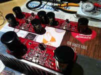
Four new FO L ready to travel the world. 🙂
Regards, L.C.

Attachments
Number 9 and 10 Modules on it;s way for me.
Nope, nr. 29 & 30 😉
And F.O. S ?
Best,
Anand.
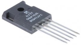
FO S is based around ALF08NP16V5 mosfet which is happen to be unobtainable, any suggestions? 🙄
Attachments
FO S is based around ALF08NP16V5 mosfet which is happen to be unobtainable, any suggestions? 🙄
Only suggestion then is the F.O. M but at a lower PS rail. What is your advice?
I certainly don't need/want 160w RMS/ch.
Best,
Anand.
Nope, nr. 29 & 30 😉
😀 You now I have built 6 x M modules and will finnish 2 x L modules mono in few days.
yes, do same as FO M but with 8amp devices and 100ma bias, as this is the major concern to multiamping I d say. cost wise this is few euro less only but ok you can make a lower price for such S version...FO S is based around ALF08NP16V5 mosfet which is happen to be unobtainable, any suggestions? 🙄
just remember one could find a pair of LJ L7 mosfet for 40 euro so if we go FO there is a reason.
yes, do same as FO M but with 8amp devices and 100ma bias, as this is the major concern to multiamping I d say. cost wise this is few euro less only but ok you can make a lower price for such S version...
just remember one could find a pair of LJ L7 mosfet for 40 euro so if we go FO there is a reason.
L7 is dangerous and with Fake components.
Preadjusted DC?
Looks like the L modul are Preadjusted. With 55 Vdc on power supply there is almost no Dc.
Looks like the L modul are Preadjusted. With 55 Vdc on power supply there is almost no Dc.
Think I killed the Large modul at once by adjustment. A spark at TP 3 and now there is 9.84 vdc between TP3 and TP4
😱😕🙁
😱😕🙁
Think I killed the Large modul at once by adjustment. A spark at TP 3 and now there is 9.84 vdc between TP3 and TP4
😱😕🙁
Between TP3 and 4 no measureable connection. Between 1 og 2 10 ohm.
Spark? Where did it came from? FO L worked perfectly on my test bench.Think I killed the Large modul at once by adjustment. A spark at TP 3 and now there is 9.84 vdc between TP3 and TP4
😱😕🙁
TP1-TP2 also TP3-TP4 resistance should be 10 Ohm. 😉
Spark? Where did it came from? FO L worked perfectly on my test bench.
TP1-TP2 also TP3-TP4 resistance should be 10 Ohm. 😉
Well it was running for 20 hours before I started adjustment. There was 45 mv at TP 3- 4. Can not see any 10 ohm resistor. Anything I can do?
Well it was running for 20 hours before I started adjustment. There was 45 mv at TP 3- 4. Can not see any 10 ohm resistor. Anything I can do?
Nothing really much you can do now, there's full bunch of SMD parts on bottom of PCB. TP1-TP2 mV adjustment should be trivial, can not imagine how a spark came into equation. Was multimeter set to A instead mV?
I consider myself experienced in this regard but I always approach to setup adjustments with max caution.
Did you like the sound in that 20 hours session or it was just powered without the signal?
Measuring Voltage TP 3 - TP 4 the leads from multimeter is right at the base of T 16. I do not like that situation. Would be Nice with a resistor in between.
Measuring Voltage TP 3 - TP 4 the leads from multimeter is right at the base of T 16. I do not like that situation. Would be Nice with a resistor in between.
Collector?
- Home
- Vendor's Bazaar
- First One - mosFET amplifier module