Got Chassis today...
Boy, that was fast!
This is a very nice Chassis, better then I expected as there is a lot one does not see in the on-line photos:
The "Standard" feet are large. 🙂
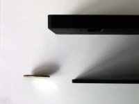
The 10 mm Aluminum Face Plate is substantial.
The 3 mm Aluminum panels are plenty rigid enough for the Hypex SMPS.
(I scaled the above with an American quarter. 😱 Sorry, I do not have any Euros.)
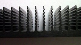
And last, but not least, the heatsinks that comes with these chassis are premium with ridged fins. 😀 ... I have no doubt now, this will be sufficient for this amp.
These chassis do ship un-assembled, which works good for this First One build, as I will be drilling and cutting holes (for the Hardware I still need to source 😱).
I was thinking of drilling a hole in the Face Plate for a power switch, but now that I see how nice it is, I am afraid to. Point being, I have not found a switch "worthy" of this chassis 😉
Boy, that was fast!
This is a very nice Chassis, better then I expected as there is a lot one does not see in the on-line photos:
The "Standard" feet are large. 🙂
The 10 mm Aluminum Face Plate is substantial.
The 3 mm Aluminum panels are plenty rigid enough for the Hypex SMPS.
(I scaled the above with an American quarter. 😱 Sorry, I do not have any Euros.)
And last, but not least, the heatsinks that comes with these chassis are premium with ridged fins. 😀 ... I have no doubt now, this will be sufficient for this amp.
These chassis do ship un-assembled, which works good for this First One build, as I will be drilling and cutting holes (for the Hardware I still need to source 😱).
I was thinking of drilling a hole in the Face Plate for a power switch, but now that I see how nice it is, I am afraid to. Point being, I have not found a switch "worthy" of this chassis 😉
Attachments

Power Switch?
I know it is in this thread somewhere... 😕
What switch does Lazy use on his build?
A link is acceptable. 😉
I know it is in this thread somewhere... 😕
What switch does Lazy use on his build?
A link is acceptable. 😉
SMPS orientation?
If I recall, Lazy done a study on the best layout of the SMPS.
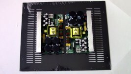
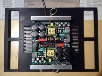
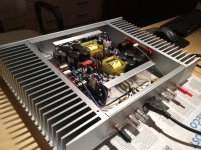
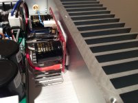
From what I can see, he lays his dual mono SMPS out horizontally, with the steel shields facing out, like in the first photo.
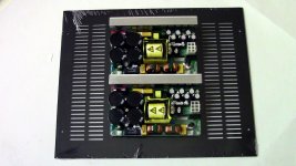
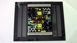
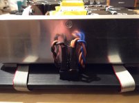
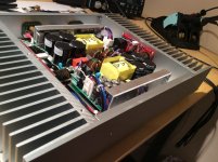
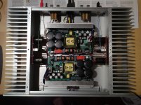
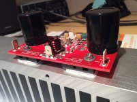
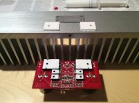
I have seen others do it vertically, like the third and forth photo.
What are the pros and cons of each arrangement, if any?
The first photo works best for the layout of the vents on the bottom panel of my Chassis.
Again, if this has already been discussed in great detail, a link is always welcome. 😉
If I recall, Lazy done a study on the best layout of the SMPS.
From what I can see, he lays his dual mono SMPS out horizontally, with the steel shields facing out, like in the first photo.
I have seen others do it vertically, like the third and forth photo.
What are the pros and cons of each arrangement, if any?
The first photo works best for the layout of the vents on the bottom panel of my Chassis.
Again, if this has already been discussed in great detail, a link is always welcome. 😉
Attachments
If I recall, Lazy done a study on the best layout of the SMPS.
From what I can see, he lays his dual mono SMPS out horizontally, with the steel shields facing out, like in the first photo.
I have seen others do it vertically, like the third and forth photo.
What are the pros and cons of each arrangement, if any?
The first photo works best for the layout of the vents on the bottom panel of my Chassis.
Again, if this has already been discussed in great detail, a link is always welcome. 😉
Hi Allen,
I think that this picture is the best layout

This allows the neatest wiring from the power supply to the modules on either side as the output DC wiring is already closest to the modules and will result in the shortest cables.
My advice is to use some 10mm male threaded hex standoff's to raise the SMPS off the chassis as this will allow you to pass the power wiring underneath the SMPS from the back to the front via a power switch and under to the mains input connectors on the power supplies which are in the centre in this arrangement.
Please do not cut a hole in the faceplate unless you intend to use a vandal proof push switch!

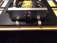
I copied LC's power switch and added a twist of my own. I mount the power switch on the bottom of the enclosure at the front ( same as LC) I then mount an LED behind in a panel mount to the bottom so the on indication is a blue glow underneath the amp. This stops the LED from boring a hole through your head when used in the dark!
As long as you use tall enough feet all you have to do is slip your finger under the front of the amp and turn it on. You can get small switches witch 4.7mm connectors that would work with the thin wires from for the Hypex mains power connectors.
Here are some examples of my amps where I have used this sort of wiring scheme.
First One Switch is a bit hidden behind the wiring but you can see the LED mounted

Stereo Hypex amp with the same wiring viewed from the top

8 Channel Hypex amp with exposed wiring for more clarity

Hope this helps.
Allen, few details to observe. 😉
Attachments
-
 First One SMPS 2.jpg380.6 KB · Views: 259
 -
 First One SMPS 1.jpg440.8 KB · Views: 290
 -
 First One SMPS 3.jpg422.4 KB · Views: 222
 -
 IMG_0505.jpg437 KB · Views: 221
 -
 IMG_0508.jpg534.5 KB · Views: 267
 -
 IMG_0512.jpg461.5 KB · Views: 282
 -
 IMG_0558.jpg424.5 KB · Views: 250
 -
 IMG_0554.jpg458.2 KB · Views: 266
 -
 IMG_0560.jpg408 KB · Views: 236
 -
 IMG_0561.jpg413.9 KB · Views: 236
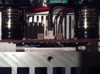
+/-48 V calibrations done
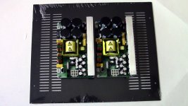
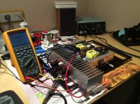
Sometimes I do custom jobs, like today's calibrations for special customer. 😎
P.S. Note 48 V serial regulators on each side of the heatsink, made according to sch above. Both 48 V rails clean as baby's booty. 😀
Sometimes I do custom jobs, like today's calibrations for special customer. 😎
P.S. Note 48 V serial regulators on each side of the heatsink, made according to sch above. Both 48 V rails clean as baby's booty. 😀
Attachments
First One S, M and L having exactly the same voltage gain +27,5 dBWill both FO1.4M and 1.4S have identical voltage gain of a +27dB?
The reason to have an equal gain lies in compatibility with system integration to bi-amping or active powered speakers.
Did-you made measurements you could share on:P.S. Note 48 V serial regulators on each side of the heatsink, made according to sch above. Both 48 V rails clean as baby's booty. 😀
The Hypex voltage drops with curents... Noise curves with charge... and the difference after extra stage ? Why 48V ? A typo, or the necessary margin to compensate Hypex 63V drop at full load (15A) ?
High-End customers have special requirements. There will be First One amplifiers running on 48 V LiPo batteries, I just saved some time so the modules could be installed in no time. Now imagine the sound when amp's PSU are fully charged LiPo batteries. 😱Why 48V ? A typo, or the necessary margin to compensate Hypex 63V drop at full load (15A) ?
Thanks for the pictures fluid and Lazy, I will study as I go...
Thanks for Your help...
I really like the vandal proof switch. They seem to have weird configurations: Off - (On) - (maybe the anti vandal part?), but I will keep looking. Basic (with these aesthetics) DPST Off - On or On - Off is what I want...
Not sure on what ratings to buy.
Each SMPS is 1200 watts, so at 125 volts, that is 9.6 amps/SMPS, so with two SMPS I need a 20 amp switch. But it does not appear the switches everyone is using is rated this high, so I have something wrong with my calculations, or I am getting something mixed up. It looks like Lazy used a DPST, which is what I was wanting to use...
Please do not cut a hole in the faceplate unless you intend to use a vandal proof push switch!
You can get small switches witch 4.7mm connectors that would work with the thin wires from for the Hypex mains power connectors.
Thanks for Your help...
I really like the vandal proof switch. They seem to have weird configurations: Off - (On) - (maybe the anti vandal part?), but I will keep looking. Basic (with these aesthetics) DPST Off - On or On - Off is what I want...
Not sure on what ratings to buy.
Each SMPS is 1200 watts, so at 125 volts, that is 9.6 amps/SMPS, so with two SMPS I need a 20 amp switch. But it does not appear the switches everyone is using is rated this high, so I have something wrong with my calculations, or I am getting something mixed up. It looks like Lazy used a DPST, which is what I was wanting to use...
The switches do not need a huge current rating as the SMPS is soft started
I really like these smaller switches from arcolectric 15A rating and only a couple of dollars, switch on transient current is something like 150A rating so they will last for a long time

H8550VBBBEN551W Arcolectric | Switches | DigiKey
The vandal proof switches are expensive for nice ones with 3A or more current rating. If you use the separate Hypex soft start board then you can use almost any momentary switch to turn the amp on or off, but that works out to be even more expensive. i.e go with the $3 hidden rocker switch!
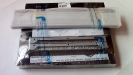
I have attached some templates I made for hole location for the First One Modules and SMPS 1200. These are word documents as I found that these were the most accurate when printed. I could not get the CAD drawing to print to scale properly. Just cut them out and line them up to mark the holes for drilling and tapping. Test first as your printer may not be the same as mine.
I used the same approach to mark the cutouts for the switch and power inlet.
I use a transfer punch set to mark the holes. They are really useful for marking drill points for speakers etc as they come in different sizes to match the hole diameter. Something like this from ebay
SHARS 28 Pcs 3 32 1 2" Transfer Punch by 64th Set Punches New | eBay
I really like these smaller switches from arcolectric 15A rating and only a couple of dollars, switch on transient current is something like 150A rating so they will last for a long time
H8550VBBBEN551W Arcolectric | Switches | DigiKey
The vandal proof switches are expensive for nice ones with 3A or more current rating. If you use the separate Hypex soft start board then you can use almost any momentary switch to turn the amp on or off, but that works out to be even more expensive. i.e go with the $3 hidden rocker switch!
I have attached some templates I made for hole location for the First One Modules and SMPS 1200. These are word documents as I found that these were the most accurate when printed. I could not get the CAD drawing to print to scale properly. Just cut them out and line them up to mark the holes for drilling and tapping. Test first as your printer may not be the same as mine.
I used the same approach to mark the cutouts for the switch and power inlet.
I use a transfer punch set to mark the holes. They are really useful for marking drill points for speakers etc as they come in different sizes to match the hole diameter. Something like this from ebay
SHARS 28 Pcs 3 32 1 2" Transfer Punch by 64th Set Punches New | eBay
Attachments
Allen, few details to observe. 😉
That looks truly beautiful !!!
Claude
Thanks for Your help...
I really like the vandal proof switch. They seem to have weird configurations: Off - (On) - (maybe the anti vandal part?), but I will keep looking. Basic (with these aesthetics) DPST Off - On or On - Off is what I want...
Not sure on what ratings to buy.
Each SMPS is 1200 watts, so at 125 volts, that is 9.6 amps/SMPS, so with two SMPS I need a 20 amp switch. But it does not appear the switches everyone is using is rated this high, so I have something wrong with my calculations, or I am getting something mixed up. It looks like Lazy used a DPST, which is what I was wanting to use...
A more sofisticated solution would be the use of a small 12V Power supply and a relay to set the smps1200 in standby mode.
Thus you can avoid the mains switch and have also remote trigger functionality.
Theodosis,
Are you proposing that the smps is always on or would you have a secondary switch to actually shut it off? I like the idea of having a sleep mode so to say so you could use an IR remote controller but I'm not sure that having the smps constantly on is the only solution.
Are you proposing that the smps is always on or would you have a secondary switch to actually shut it off? I like the idea of having a sleep mode so to say so you could use an IR remote controller but I'm not sure that having the smps constantly on is the only solution.
The 2U 300mm Dissipante is the right choice to keep the modules at 45 degrees, you can have the whole case made will aluminium panels as an option and this will transfer some of the heat from the sinks to those panels as well and the 10mm thick front panel is also a pretty big chunk of aluminium.
You can get bigger sinks if you want but you will be moving further away from LC's recommendations by doing so. If you plan to beat the life out the amp with low ohm loads bigger heatsinks make more sense. Do you actually know how much power you will need?
Hi guys, I just ordered THE FO and a pair of nice hypex 1200A400. But now I am wondering what kind of casing (heatsink) I should buy. The FO is going to be connected to my nice QUAD electrostatic speakers ESL-2905.
Would it be better to order the Dissipant 3U 400...?
This based on Fluid's info above: "If you plan to beat the life out the amp with low ohm loads bigger heatsinks make more sense."
Quad 2905 is not a really low impedance speaker. Factory specifies impedance as lying between 4 and 20 ohms. So no problems here.
Theodosis,
Are you proposing that the smps is always on or would you have a secondary switch to actually shut it off? I like the idea of having a sleep mode so to say so you could use an IR remote controller but I'm not sure that having the smps constantly on is the only solution.
Applying an external 5V DC voltage to pin J5.1 will put the SMPS1200 in standby.
Of course you must use a small switch or a remote control or a remote trigger to provide this 5V to pin J5.1
Thanks Theodosis,
Is that pin 25 connection only applicable to the Hypex smps or do most smps have this same type of function to go to standby? I realize you may not know the answer to this question so if anyone knows these smps and how they are generally configured it would be a nice fact to know.
Is that pin 25 connection only applicable to the Hypex smps or do most smps have this same type of function to go to standby? I realize you may not know the answer to this question so if anyone knows these smps and how they are generally configured it would be a nice fact to know.
Thanks Theodosis,
Is that pin 25 connection only applicable to the Hypex smps or do most smps have this same type of function to go to standby? I realize you may not know the answer to this question so if anyone knows these smps and how they are generally configured it would be a nice fact to know.
My SMPS has a standby input and a DC Error detect input, not all SMPS have such fearures
Thanks Cresnet. I only wish you made an inline power supply, I'm trying to keep the power supply outside my powered speaker design. I'm hoping to find something that will be good for audio applications that would already be UL/CE approved to take that out of the equation. For the Slewmaster amp I have to build I'd take a look at what your building but that is for my own useage. I also have a pair of LC's earlier amps before the First One came along I need to put to work somewhere.
- Home
- Vendor's Bazaar
- First One - mosFET amplifier module