I did not realize the ALF was already isolated, so I just used the same plastic shoulder washer everywhere. I think I will take that out now, the Alfets should have a good tight connection. I have seen that ground circuit on Rod's web site, I normally use almost the same ground scheme but w. discrete diodes.
Very interesting about the transformer!
I have seen similar transformers used in some medical instruments to reduce the magnetic field to essentially zero, but they are usually lower power, and too expensive for diy projects. I have a semi-custom transformer from the recent "Primrose" GB, but it has a mechanical hum, so I am using it just for testing the PSU right now. (Post 487 above)
Mine was not too expensive, I paid less than 200EUR for 2 trafo's like that, shipping included from PL to NL. More detailed description is here.
Of course shipping to U.S. is prohibitive in this case, because of size and weight, but I am sure you can find similar products around you.
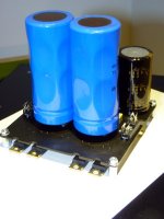
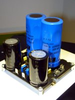
It works!!! it sounds GORGEOUS! It was so difficult to stop it to be able to mount the indicators and the top cover!
As mentioned in the main thread as well, i am thrilled by the silence it "provides" to the loudspeakers. With the cap multiplier set to approx 600mV drop, the ripple present on the huge caps is totally vanished at the circuit power supply input points. Many thanks for making this public Mr.Evil and PMI for adapting it to VSSA. I guess it can be the secret weapon. i am tempted to see how it sounds without it, but ...hell... who can stop this beast singing? 😀 😀 😀
Of course, I will now have a reference for my future build, the balanced one. Not decided yet about the primal supply (trafo or SMPS) but I will use for sure this wonderful Cap multiplier.
Cheers!
I am very happy to hear that, 🙂It works!!! it sounds GORGEOUS! It was so difficult to stop it to be able to mount the indicators and the top cover!
As mentioned in the main thread as well, i am thrilled by the silence it "provides" to the loudspeakers. With the cap multiplier set to approx 600mV drop, the ripple present on the huge caps is totally vanished at the circuit power supply input points. Many thanks for making this public Mr.Evil and PMI for adapting it to VSSA. I guess it can be the secret weapon. i am tempted to see how it sounds without it, but ...hell... who can stop this beast singing? 😀 😀 😀
Of course, I will now have a reference for my future build, the balanced one. Not decided yet about the primal supply (trafo or SMPS) but I will use for sure this wonderful Cap multiplier.
Cheers!
(and quite envious of that Pre Build!)
Hi Pete, just finished aussie amp modules nvx200 with CM and sounding fabulous. 😀
Quan
Any link for those nvx200 amp modules? Is it 200W power?
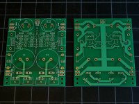
Single-Layer Layout
One version of the layout that I hope is suitable for etching is attached below.
I have actually made a couple other versions on request, but so far there has not been much feedback, and I do not normally etch boards at home... In other words, until someone else provides a little feedback, please use at your own discretion.
I believe this version is the easiest to etch, and almost identical to the 2-layer circuit board. One of the optional ground connections has been dropped, and one jumper added, to keep the other components in the same locations.
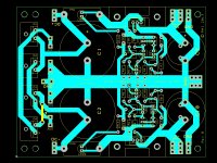
I am also posting pics of the two-layer, and the single layer version side-by-side for comparison.
@Idefixes: If you are reading this, please review and comment, since I believe you have both versions (?). Thanks.
One version of the layout that I hope is suitable for etching is attached below.
I have actually made a couple other versions on request, but so far there has not been much feedback, and I do not normally etch boards at home... In other words, until someone else provides a little feedback, please use at your own discretion.
I believe this version is the easiest to etch, and almost identical to the 2-layer circuit board. One of the optional ground connections has been dropped, and one jumper added, to keep the other components in the same locations.
I am also posting pics of the two-layer, and the single layer version side-by-side for comparison.
@Idefixes: If you are reading this, please review and comment, since I believe you have both versions (?). Thanks.
Attachments
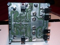
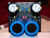
CapMu DIY single layer "Black Edition". I swap from top to bottom the Rled with 1W 2512 SMD part.
Marc
Marc
Attachments

Last edited:
I like it! What size is the board?CapMu DIY single layer "Black Edition"....
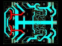
You have 11 tappings into the Ground trace between the two sets of big caps.One version of the layout that I hope is suitable for etching is attached below...........
This must contravene the rule: do not share a trace with different currents.
You have 11 tappings into the Ground trace between the two sets of big caps.
This must contravene the rule: do not share a trace with different currents.
I suppose that every pcb that aspires to practicality must include some compromises.🙂
But too big compromises are usually avoidable.
The results of too big compromises could be reduced performance.
The results of too big compromises could be reduced performance.
Thanks for the comment. It probably does violate that rule, but the performance does not seem to be affected, to the best of my ability to hear, or to look for the noise on the output with a 100 MHz scope. Can you possibly suggest a test I can do, other than looking for noise on a scope, or listening? Any noise on the rails is below what I can measure.You have 11 tappings into the Ground trace between the two sets of big caps.
This must contravene the rule: do not share a trace with different currents.
In the beginning did have a version with five different ground traces, but they were not very wide, and I anticipated there might be other issues if I made the grounding scheme more complicated. I originally experimented with having a separate return for the filter circuit ground on one rail, leaving the grounds for the other rail common. I could not tell a difference.
R11 connect direct to Q11 source.
C3 to R3
R9 to Q11 trace
R3 to Q11 trace
Q11 trace to output, AT THE OUTPUT.
repeat for lower half.
C3 to R3
R9 to Q11 trace
R3 to Q11 trace
Q11 trace to output, AT THE OUTPUT.
repeat for lower half.
I think what this basically adds up to you are recommending a separate connection for the filter circuit, from wherever the ground terminals are, if I read the meaning of "OUTPUT" correctly?...
Q11 trace to output, AT THE OUTPUT.
repeat for lower half.
All the components that I listed share traces with the main input to output Zero Volts line.
The C3 fairs even worse !
As such all these components are picking up interference that can easily be avoided by improving the layout.
The C3 fairs even worse !
As such all these components are picking up interference that can easily be avoided by improving the layout.
I think I was basically asking if I understoon one line in your comments, correctly (?)
Q11 trace to output, AT THE OUTPUT.
- Status
- Not open for further replies.
- Home
- Amplifiers
- Power Supplies
- Finished capacitance multiplier