it would be worth adding the "ripple eater" to the comparison.I have now readed all the posts with allot of interest.. I am curious to find out (if someone could help us with a simulation) to see a comparation between this cap multiplier with the newer components (the updated version) and the one sugested by JLH hymself for his highly biased versions of class A amplifiers (from the picture from below). This would be interesting to see, because we have two circuits with potential and i think it is very importanty to see how they compare in therms of ripple, regulation, heat etc. I am really curious to see how they behave with high current eaters (like F5T, Aleph's,DoZ, JLH for Quad ESL).
Below (in the picture) are the minimum values for C1&C2 indicated by JLH for his cap multiplier.
All these circuits do a similar ripple attenuation, without the "regulation" that comes with a true voltage regulator
Since there is no loop feedback in the JLH multiplier the output impedance will go higher towards the lows. Bigger output shunt caps can reduce that.
Soft Start
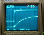
For myself, one of the "winning" characteristics of this particular Cap Multiplier was the soft turn-on (meaning the rail voltages come up gradually).
O-scope screen shots of some of my tests were posted above, but I am reposting this one below for illustration.
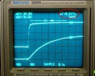
1) In the first picture, the cursors of the storage scope are set to measure the normally fast voltage change before the CM filter. This is fast enough that if the amplifier is predisposed to transmit the resulting transient to the output, you will hear some kind of startup noise.
2) In the second picture, the scope is set to measure the slower voltage change at the output of the Cap Multiplier. In most cases, this will push any startup transient down to the sub-sonic frequency range... in other words, no startup noise, or at least none contributed by the power supply.
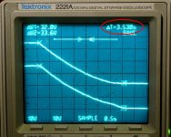
3) Third pic is the shutdown, posted for completeness.
Note: If you already have soft-start and muting circuitry, this may not be relevant from the standpoint of what you hear from the speakers, however I personally believe that a well-behaved start and shutdown is one of the benefits.
For myself, one of the "winning" characteristics of this particular Cap Multiplier was the soft turn-on (meaning the rail voltages come up gradually).
O-scope screen shots of some of my tests were posted above, but I am reposting this one below for illustration.
1) In the first picture, the cursors of the storage scope are set to measure the normally fast voltage change before the CM filter. This is fast enough that if the amplifier is predisposed to transmit the resulting transient to the output, you will hear some kind of startup noise.
2) In the second picture, the scope is set to measure the slower voltage change at the output of the Cap Multiplier. In most cases, this will push any startup transient down to the sub-sonic frequency range... in other words, no startup noise, or at least none contributed by the power supply.
3) Third pic is the shutdown, posted for completeness.
Note: If you already have soft-start and muting circuitry, this may not be relevant from the standpoint of what you hear from the speakers, however I personally believe that a well-behaved start and shutdown is one of the benefits.
Attachments
Rectifier Diode Selection
The Capacitance Multiplier PCB can be used over a fairly wide range of voltages and currents, but components have to be selected with appropriate ratings.
In the case of the rectifier diodes, average current rating, peak current rating, and maximum reverse voltage have to be observed. To put it another way, the rectifier diode should be selected the same way as any other linear supply, CM or not.
The average current depends on the amplifier, but the peak current depends on the size of the reservoir capacitor. The larger the reservoir cap, the greater the momentary current generated when the cap is charged.
The reverse voltage rating of the diode is given roughly by the maximum pk-to-pk voltage at the transformer secondary.
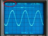
Example, using my transformer with a nominal 25V secondary winding:
(25V(rms) * Sqrt(2) * 2) * 1.05 - 0.7 ~~ 73.5V
This is the reverse voltage seen at the rectifier diode.
Picture below shows voltage measured at light load. The bottom of the waveform represents the period when the diode is conducting. The top of the waveform represents the period when the opposite polarity diode conducts current to the other rail, and the reverse voltage is at its maximum.
The Capacitance Multiplier PCB can be used over a fairly wide range of voltages and currents, but components have to be selected with appropriate ratings.
In the case of the rectifier diodes, average current rating, peak current rating, and maximum reverse voltage have to be observed. To put it another way, the rectifier diode should be selected the same way as any other linear supply, CM or not.
The average current depends on the amplifier, but the peak current depends on the size of the reservoir capacitor. The larger the reservoir cap, the greater the momentary current generated when the cap is charged.
The reverse voltage rating of the diode is given roughly by the maximum pk-to-pk voltage at the transformer secondary.
Example, using my transformer with a nominal 25V secondary winding:
(25V(rms) * Sqrt(2) * 2) * 1.05 - 0.7 ~~ 73.5V
This is the reverse voltage seen at the rectifier diode.
Picture below shows voltage measured at light load. The bottom of the waveform represents the period when the diode is conducting. The top of the waveform represents the period when the opposite polarity diode conducts current to the other rail, and the reverse voltage is at its maximum.
Attachments
The simplest choice for rectifier diodes is to use some with high reverse voltage as Fast Recovery MUR 860. They are cheap, have much higher reverse voltage than Schottky diodes and many people use them for audio power amp supplies. If you buy more of these you can use them in different projects for PSU.
I shall use IXYS DSEI 8-06A fast recovery diodes for my Cap Multiplier. These have high reverse voltage (600V) but also "soft recovery behavior" and "low noise switching". The only drawback is forward voltage loss which is 1,5V so for class A amp there will be more heat to dissipate.
I shall use IXYS DSEI 8-06A fast recovery diodes for my Cap Multiplier. These have high reverse voltage (600V) but also "soft recovery behavior" and "low noise switching". The only drawback is forward voltage loss which is 1,5V so for class A amp there will be more heat to dissipate.
Be careful. There are many expensive diodes fakes on the market, simply repacked ordinary diodes. Local shop which sells it used to sell fakes from time to time.The simplest choice for rectifier diodes is to use some with high reverse voltage as Fast Recovery MUR 860. They are cheap, have much higher reverse voltage than Schottky diodes and many people use them for audio power amp supplies. If you buy more of these you can use them in different projects for PSU.
I shall use IXYS DSEI 8-06A fast recovery diodes for my Cap Multiplier. These have high reverse voltage (600V) but also "soft recovery behavior" and "low noise switching". The only drawback is forward voltage loss which is 1,5V so for class A amp there will be more heat to dissipate.
Be careful. There are many expensive diodes fakes on the market, simply repacked ordinary diodes. Local shop which sells it used to sell fakes from time to time.
Thank you for the comment. It seems that I bought fakes. Original IXYS DSEI8-06A diodes should have Vf=1,5V at 25C and 8A current. I measured only 0,55V with my DMM. I already soldered four of these on my cap multiplier pcb. Should I remove them and use something else?😡
If you measured at no load, using the diode setting of a multimeter, that might be about right. Diodes can have a very low forward voltage drop at close to zero forward current, even if they exhibit much higher forward voltages at closer to rated loads. The reading can also be thrown off by a weak battery in the meter, by poor resolution some meters have on that setting, etc. For example, if your meter is not capable of measuring resistance below 1 ohm well, there is a good chance that the diode readings will be off a bit.Thank you for the comment. It seems that I bought fakes. Original IXYS DSEI8-06A diodes should have Vf=1,5V at 25C and 8A current. I measured only 0,55V with my DMM. I already soldered four of these on my cap multiplier pcb. Should I remove them and use something else?😡
We mostly assume that power diodes will have a small change in forward voltage over a large forward current range, but when operating below 10% of rated current, that is usually not the case.
For comparison, out of circuit, the Schottky diode I am using measures around 0.25V with a conventional multimeter on the diode setting.
Pete, that's good news to my ears. Shop owner is my friend and he is certainly not trying to sell me fakes. He told me exact distributor where he got these diodes and it's Schukat in Germany. My DMM is certainly not capable of measuring resistance below 1 ohm well and, yes, I used diode setting. So, after all, these may be originals.
It is possible that he even does not know if they are fakes. Even German distributors sell fakes sometime, I am speaking from my experience.Pete, that's good news to my ears. Shop owner is my friend and he is certainly not trying to sell me fakes. He told me exact distributor where he got these diodes and it's Schukat in Germany. My DMM is certainly not capable of measuring resistance below 1 ohm well and, yes, I used diode setting. So, after all, these may be originals.
They are most probably genuine parts, but if they are not, you have something like 1N5402 in TO-220 package, which is not that bad.
It is not easy for amateurs to test diodes ,to be sure.Exotic parts are "fakeable",it is only which I wished to say.
Personally, I would use BYW29-200 diodes for audio PS, which are much cheaper and with good specifications and less attractive for bad boys.
Non original parts are the main enemy of DIY audio.
BYV 29s are a bit 'softer' sound - you can also get them with the insulated body so easier assembly
Ivan, (and anyone we have now scared who is running home to check their diodes...):
For comparison, I measured two diodes which came from Mouser, and one which came directly from ON Semiconductor as a sample, with a conventional meter.
MBR10T100: 0.240V (original Schottky diode I used for testing)
MBR10100G: 0.236V (On Semi, Mouser)
MSRF860G: 0.412V (On Semi, plasti-pak sample)
The last one was the "Soft" turnoff diode recommended earlier in this thread. The readings will vary a bit depending on the meter, so what is important here is not so much the accuracy of the no-load forward voltage, but that they all produce similar readings at no load. According to the datasheets, the last one should be closest to what you have, and in fact the readings are only 0.15V apart.
I have never used the MSRF860G, but there is no question about that batch of parts. They came directly from ON Semiconductor in the US, with the usual On-Semi packaging, correspondingly high shipping charges, and over-the-top paperwork... (figure $2 for each "free" sample 🙄 )
P.
AFAIK, the only way the rectifier diodes will produce a "softer" v. "brighter" sound is as a result of two potential problems combining to make the "brighter" of the two.BYV 29s are a bit 'softer' sound - you can also get them with the insulated body so easier assembly
First, the turnoff noise of the diode has to make it past the power supply. If this turns into common mode noise, as switching noise is likely to do, it becomes more noticable.
Second, the CMRR of the amp circuit is poor, so the noise combines with the audio signal, and makes "smooth" sounds appear more edgy and brighter. Basically, the noise is added to the signal, and especially at the peaks, it produces a metallic-sounding tone. In extreme cases, it can make an acoustic string instrument sound like an electric guitar, or a clarinet sound like a horn. For a simulated example, look at some graphs posted in the VSSA thread Esperado's Simulations and scroll down to the CMRR section.
Those two trim pots set the drop voltage across the pass transistor (Vdrop). Similar to the dropout voltage in a conventional regulated power supply.OK I did a search for this but can't find it. What is the procedure for adjusting VR1 & VR2?
This is normally set according to the expected amplitude of the ripple voltage to be filtered. For a class A-B amplifier anywhere from 0.75V~1.5V, depending on the power output, expected ripple, and so on.
For example, set the output voltage to +35V, and -35V, when the unregulated supply voltage is approximately +/-36.2, measured at the fuses. Resulting Vdrop is 1.2V.
There are a couple different ways to set this.
a) You can measure the drop from the fuse to the output directly, and set to the desired Vdrop voltage.
or
b) measure the unregulated +/- voltage at the fuses, write it down, then measure the output, and adjust the output voltage until it is smaller than the unregulated voltage by the desired amount.
The voltage should be set with at least a minimal load, not open-circuit.
Both rail voltages should be checked again after connecting to the amplifier, at idle, and if necessary adjusted to the same value.
Sorry, the differences to the sound when using different diodes is small, quite small, particularly in comparison to the difference in output caps (as has been mentioned before), and this cct buries a lot more of the offending 'noise' than a passive filter cct feeding low PSSR classA amplifiers, for example.
I wouldn't get too hung up on the type of diodes, but focus instead on the caps - the difference in sound between say, a BHC on the output and a Mundorf, Roe, Phillips, F&T, etc and also between Sprague, Panasonic, Nichicon, Elna, etc is quite noticeable and this will directly effect the following cct, even if you use 'junk parts'.
This is 'according to me' (!) and not everyone will agree!!
James, I would think that in this case, it should just be the output cap that is important, even in the case of Class-A don't you think?...focus instead on the caps - the difference in sound between say, a BHC on the output and a Mundorf, Roe, Phillips, F&T, etc and also between Sprague, Panasonic, Nichicon, Elna, etc is quite noticeable...
Last edited:
Hi Pete,
Thanks for the answer. I still have a question. You stated this,
How do you determine the "desired amount"?
I have never used this type of capacitance. I have always just used caps and resistors so I didn't want any more drop in voltage that I had to.
Thanks
Thanks for the answer. I still have a question. You stated this,
adjust the output voltage until it is smaller than the unregulated voltage by the desired amount.
How do you determine the "desired amount"?
I have never used this type of capacitance. I have always just used caps and resistors so I didn't want any more drop in voltage that I had to.
Thanks
Hi Pete,
Thanks for the answer. I still have a question. You stated this,
How do you determine the "desired amount"?
I have never used this type of capacitance. I have always just used caps and resistors so I didn't want any more drop in voltage that I had to.
Thanks
We need some kind of rule of thumb to predict aprox ripple for unregulated supply voltage (at fuses) and with such rule we can adjust a little bit more than this to be sure.
- Status
- Not open for further replies.
- Home
- Amplifiers
- Power Supplies
- Finished capacitance multiplier