Terry: You cannot make a good measurement with no load, or adjust the Vdrop with no load.
As the load increases, so does the ripple before the filter, in proportion to the load. You can see some examples I posted above, with measurements. So, as you increase the load, the AC measurement before the filter increases. The AC measurement after the filter, should stay close to zero.
As the load increases, so does the ripple before the filter, in proportion to the load. You can see some examples I posted above, with measurements. So, as you increase the load, the AC measurement before the filter increases. The AC measurement after the filter, should stay close to zero.
Hi Pete,
I did set it with a load earlier. The last time when I checked it there was no load. If you will finish your newest PeeCeeBee design I will have something else to check it with. 😉
I did set it with a load earlier. The last time when I checked it there was no load. If you will finish your newest PeeCeeBee design I will have something else to check it with. 😉
Outch! (working on it)Hi Pete,
I did set it with a load earlier. The last time when I checked it there was no load. If you will finish your newest PeeCeeBee design I will have something else to check it with. 😉
In any case, the design is LC's and Shaan's, I just push some parts around on the screen, and hope the folks at the board house can make it look pretty 🙄

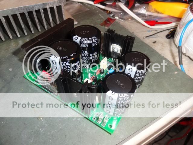
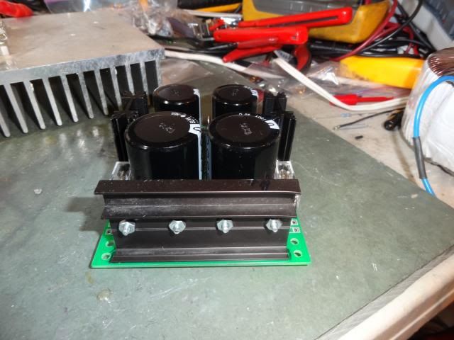
My finished capacitance multiplier.
 finally built, great!
 How tall are the heatsinks?
(they seem taller than what I can find at Mouser.com... 😉 )
Yes, looks like the same extrusion as I listed in the BOM, with a couple extra holes.
Aavid-Thermalloy/513102B02500G
There is nothing special about the part number. As long as the footprint and the pin spacing is the same, it will fit. Even if you select a heatsink that does not fit the footprint exactly, it will still work if it is about the same size and surface area. At lower power levels, even a 2~3 square inch of aluminum plate will work just fine.
How tall are the heatsinks?
(they seem taller than what I can find at Mouser.com... 😉 )
Heatsinks are 50 mm tall (2 inches). I think these are the biggest heatsinks in this style. I think that they are rated 9degC/W.
Yes, same as the maximum size with that footprint that I found at Mouser. The picture makes them seem bigger.Heatsinks are 50 mm tall (2 inches). I think these are the biggest heatsinks in this style. I think that they are rated 9degC/W.
Have you guys experienced much heat on any of the heatsinks. I put a single heatsink across the diodes anticipating some heat there, but to be honest, I don't feel any heat anywhere. I'm driving the Symasym as loud as I can stand it and there is really no heat at all. I'm using a 25-0-25 600VA transformer and the rails are sitting at 37.8VDC. I'm running about 70ma bias on the Symasym. What would you be running that would cause this to need these big sinks?


70mA to each polarity with 1.2V of Vdrop across the Pass Transistor amounts to ~84mW being dissipated in each device.
That is going to raise the heatsink temperature by how much?
Putting your hand/fingers on the heatsink will heat it more.
The average power put out by your amplifier is usually very low in comparison to the maximum. It's that average power that is the demand put on your Cap Multiplier.
Try measuring the average current passing through the Cap Multiplier when you listen at various volumes.
Hi,Terry: You cannot make a good measurement with no load, or adjust the Vdrop with no load.
As the load increases, so does the ripple before the filter, in proportion to the load. You can see some examples I posted above, with measurements. So, as you increase the load, the AC measurement before the filter increases. The AC measurement after the filter, should stay close to zero.
Have been following this thread (sometimes),seem a clean product.
I have some confusion with the regulator Mr. Evil, is equal to this? . I saw some of your measures, regard to noise & ripple, are very good.
I'm curious to see (if possible and/or if you have them measured), the response of this regulator (voltage drop under burst), also with medium current as 3-4 Amp.
regards
For a rough estimate, assume:Have you guys experienced much heat on any of the heatsinks. I put a single heatsink across the diodes anticipating some heat there, but to be honest, I don't feel any heat anywhere. I'm driving the Symasym as loud as I can stand it and there is really no heat at all. I'm using a 25-0-25 600VA transformer and the rails are sitting at 37.8VDC. I'm running about 70ma bias on the Symasym. What would you be running that would cause this to need these big sinks?..
Ambient temp. = 50C
Max. junction temp. = 175C
Junction-to-ambient themal resistance with no heatsink = 60C/W
Diode forward voltage drop = 0.5V
This gives a max. allowed temp. rise of 125C, which will occur with 2W of power, which will happen with an rms current of 4A (per diode). Anything up to that could potentially be done without diode heatsinks.
There's a lot of assumptions in there, but it will give you a rough idea. Nonetheless, even if you don't use that much power, it's still good to keep schottky diodes extra cool, because it keeps their reverse leakage current down.
I don't have anything more than I have already posted, and I can't remove my own PSU to take any more measurements now. However, I'm sure that more measurements will appear now that there are lots of PCBs out there. If you want good transient response, a large (PMI's specified 4700u is plenty), low impedance output capacitor is what matters most....I'm curious to see (if possible and/or if you have them measured), the response of this regulator (voltage drop under burst), also with medium current as 3-4 Amp...
Hi,
to Mr.Evil:
thanks for the reply, Ops!..sorry now realized that this is your regulator.
I thought it was of Pmi,..my wrong.
to Mr.Evil:
thanks for the reply, Ops!..sorry now realized that this is your regulator.
I thought it was of Pmi,..my wrong.
It does not need a big heatsink, but some heatsinks are a minimum requirement, taking into consideration temps inside some chassis, higher bias currents than you are running, etc....What would you be running that would cause this to need these big sinks?...
A small Class-A amp will generate more heat in the heatsinks than a large Class-AB amp. The same thing applies to a Class A-B with a high bias. A single heatsink is more suitable to those situations.
My VSSA uses about 300mA when idle with a single pair of output devices. The two-pair version of VSSA will use close to double that, and I am sure some people will try to run it at higher current (consider some of the experiments being done by Idefixes).
Aside from that, I wanted to make sure that nobody ran into trouble running test tones, into dummy loads, etc. See a post by Rick G in the VSSA thread.
This is not just a matter of large continuous forward current, but protecting a Schottky diode as it gets close to the reverse breakdown voltage. Schottky diodes are happier running cool... 😀
Thanks Guys,
I was just wondering if I did something wrong. I drove the amp to clipping. It pulled the voltage down to 36V fro 37.8. Still the heatsinks weren't warm. My ears were bleeding though. I'm certainly not saying that it is not a good idea to protect them. I was just wondering if guys were worrying a little too much about the size.
I'm running both channels and they are set at 70mA each per specs. I don't have anything that is apart that I can test it with. I suppose I could hook up a light bulb and see what that does but last time I tried that I couldn't hear anything. 😀
You have an amplifier with a fairly low bias current, so that is not surprising....I drove the amp to clipping. It pulled the voltage down to 36V fro 37.8. Still the heatsinks weren't warm...
The way to prove to yourself that the Cap Multiplier is doing some good is to leave an amplifier connected to the PSU, and load the power supply at the same time.
If you want to use lightbulbs or other dummy loads, you put them in parallel with the amp load, not instead of the amp.
With a conventional power supply the ripple and switching noise become more audible at idle, because the lightbulbs have increased the load current.
With a highly filtered supply, Cap Multiplier or other type, there is no noise, the output is just as silent as without the added load.
High current at idle and at very low volume are the conditions normally seen only with Class-A, which is why Class-A amps often have such big capacitor banks.
With Class A-B, that level of power supply noise only happens at high volume, because the ripple and switching noise increase with current. The effects are usually not noticed, or dismissed as other distortion. That does not mean they are absent, just that we cannot easily identify them, and they occur at levels well below clipping.
That is a true statement as far as it goes, but it is not the whole story. We may not be able to hear a frequency above 20KHz, but in most cases, we still care about the performance of the amp above 20 KHz, because it has an effect on the accuracy with which the sound is reproduced. The good qualities of VSSA include extended frequency range and high slew rate. If nothing above 20KHz mattered, we would not care about that.The advantage I see is that the SMPS had its ripple frequency above the audio band and thus shouldn't have an audible effect on the VSSA's performance...
High frequency switching noise will modulate the audio signal in ways that alter what we hear. One of the first things that LC did was modify the Hypex SMPS with larger and better quality capacitors, to reduce the high frequency ripple.
LC first had to go up to 40 millifarad per channel (!) with a conventional power supply to get performance he liked.
VSSA Post #630
Later, the PSU became an SMPS (two of them, actually), but without additional modification, this proved to have a huge voltage sag at full load (3.5V), and lots of high frequency ripple (2.5V pk-pk) It required recapping a brand new power supply to cut that in half.
VSSA Post #1048
The reason for this is not because the SMPS is a bad design, from my reading it is about as good as you can expect, but the components used are inexpensive (small Samwha caps, small heatsink). It is also specified by the manufacturer for class D use, and the specified (from datasheet) continuous power output is only a fraction of the maximum current... All perfectly fine for Class D amplifiers, which are very efficient. Not so much for more power-hungry Class AB, and definitely not for Class AB with high bias, or even small-ish Class A.
VSSA Post #1295, SMPS Recap
Aside from that, there are inherent issues with SMPS use that may not be obvious from reading the datasheets, like putting a source of 50-100KHz radiated noise next to a high-gain circuit which is already sensitive to EMI, a hellacious inrush into your amplifier at turn-on, and failure modes which are not easy to resolve with typical DIY tools.
VSSA Post #2306
Having said all that, Switch Mode Power Supplies have lots of advantages:
1) No added transformer cost
2) Small size and weight, and therefore, small shipping cost, smaller/lighter chassis, etc.
3) Low production cost.
4) Low environmental impact. Little copper mined, better efficiency, lower disposal cost.
5) Less heat generated inside the chassis.
6) Basically disposable if they fail, or when the caps start to leak.
7) Easier to turn into a sealed external supply (A "brick" type supply is usually an SMPS, not a linear supply).
Hi Pete
I sit with heatsinks, 2xHypex, and your pcb's, just waiting VSSA's (You know ALF's).
I been suggested by ESPARADO to do test when times come, by combining hypex with your pcb's, what do you think, will we gain something ?
Just answer if you got time and interest, i respect you are involved many threads.
Regards Ricky
- Status
- Not open for further replies.
- Home
- Amplifiers
- Power Supplies
- Finished capacitance multiplier