IvanLukic(4)
Freeman(2)
Idefixes(4)
Touchdown(2)
vgeorge(2)
Jameshillj(2)
Jsixis(2)
Praudio(2)
Compressit(2)
Cambe(2)
Gannaji(1)
Potepuh(4)
Syklab(2)
quan(4)
tjencks(2)
BYRTT(4)
Ryssen(2)
rickmcinnis(3)
Joachim Gerhard(2)
still4given(2)
Rick G(2)
androa76(2)
fredlock(2)
stajo(4)
kimon(2)
SigFire (2)
vitalica(4)
dw1narso (2)
analog_sa(2)
buzzforb(2)
kindhornman (6) as long as it will be next month, blew my budget this month already!
Luke(4)
pchw (4)
jj506 (4)
TheShaman (2)
Raj1 (6)
Ranchu32 (2)
Pinnocchio (2)
mine are on the way, may take me a few weeks to round up all the pieces and parts but I am looking forward to these.
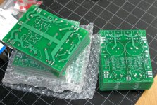
PCB Status
Most of the boards in the current order are due to arrive tomorrow (although I may not see them until Thr), with a few following a few days later, because the order quantity was increased.
Please note that I have created a separate thread in the Group Buy Forum for the board orders, updated documentation, updated BOM, etc. The Mouser BOM is being revised, and will be posted there, so will any future component availability issues or changes.
http://www.diyaudio.com/forums/grou...-capacitance-multiplier-power-supply-pcb.html
Please make any changes/additions to the list of names there, thank you. Discussion not related to the board orders, or to the documentation, should stay here, if possible.
The BOM has been edited to show the generic part number for the Schottky rectifier diode. D1-D4 is now listed as MBR10100, still 10A, 100V, TO-220AC. This is a generic part number for a 2-lead diode in a TO-220 package.
Examples:
Mouser, ON Semiconductor, MBR10100G, $1.13
Newark, Multicomp, MBR10100, $0.22
Diodes other than Schottky will work also. Alternative, high voltage soft-turnoff diode:
Mouser, ON Semiconductor, MSR860G/MSRF860G, $1.16/$1.07
Pinnocchio, you left off Raj1 and myself when you updated the list :-(
Sorry mate! I just took the last list that was updated and added my name... Please add your name to the list next time to make sure it does not happen again... In reality I just wanted to bypass the both of you! 😀 ... Not!

Do
Figure around $66, give or take pennies.What will be the final costs for 6 boards and shipping to California?
$10/board, plus $3 shipping, padded envelope, Paypal. Couple dollars more if you want them shipped in a small flat-rate box.
Thanks, Terry!Paypal sent for my two boards.
Thanks, Terry
Someone else was going to do that too, and I am supposed to build one for a local friend as a lower current fixed voltage version. Fortunately, MrEvil has made that easier for us... see Post 186.
I decided to re read this thread
Thanks. That was over my head and I was wondering if I should try that.
PMI how much capacitance is delivered at the output of this wonderfull design?
Dear colleagues , i am not so experienced in developing new schematics or in modifying them, so i am asking you if we cand colaborate in developing this schematic for using it in class A?
If we scale it to a Le Classe A amp @30W (by J.H) then it will be usable in all kind of class A amps because this amp requires about 700.000uF of capacitance.
I think that there are allot of people out there who didnt build a class A amp because of the expensive bank of capacitors.
What do you say guys (PMI, Mr Evil, and the others)?
Thanks in advance.
Ps:excuse my rougue english.
It behaves more like an RC filter, so it's not really equivalent to an amount of capacitance, but I just did a quick simulation to get a rough idea. The capacitance multiplier gives about 4mV p-p ripple at 2A output current. To get a similar amount of ripple with an actual capacitor, it would have to be around 4F (a lot more than your required 700 000uF).PMI how much capacitance is delivered at the output of this wonderfull design?..
I would be happy to help if I can. However, jameshillj (see his posts above) is already trying to do just that with a version of the F5. James has two of my first boards in his hands now, so you can perhaps ask him for some tips or comments.If we scale it to a Le Classe A amp @30W (by J.H) then it will be usable in all kind of class A amps because this amp requires about 700.000uF of capacitance.
I think that there are allot of people out there who didnt build a class A amp because of the expensive bank of capacitors.
What do you say guys (PMI, Mr Evil, and the others)?
Thanks in advance.
One of my local friends is looking into what it would take to make a version for high continuous current (which is basically what you need for most Class-A amps). If necessary, I will make some layout/component changes to make this easier.
@MrEvil: Thanks for the simulation results! Nice to know my tests track with the theory.. 🙄 😀
I am not an expert on class-A amps, so the following probably needs a "sanity check"...
@sergiu: A power supply for Class-A has to work much harder than a power supply for Class A-B. The filter is just part of it.
The higher the continuous, or "quiescent" current, the more heat is dissipated in the power supply, both in the rectifier diodes, and in the pass transistors. (In the transformer too, obviously.) So compared to class A-B which has a modest bias current, this may require bigger heatsinks and some other changes.
The ripple at idle measured before the pass transistor will increase in proportion to the idle current. The voltage drop for the pass transistor has to be set higher, to allow for the greater ripple, or the value of the first filter cap must be increased, or both.
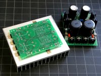
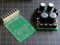
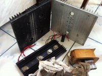
Greater voltage drop across the pass transistor, in combination with higher continuous current, means much more heat. The 11 C/W rated heatsinks I am using are not going to be enough. I believe you will need 5-7 C/W rated heatsinks or better, because the inside of a class-A chassis is expected to be much warmer than class A-B.
This is why I laid out the board to allow the diodes and pass transistors to mount from the bottom, and attach to a common heatsink, or to a flat aluminum plate. See pics below for an illustration. The heatsinks in the pics are overkill, but they are very inexpensive extrusions, not finished parts.
Attachments
This is interesting. I hope you guys take this farther. It would be great if these could do class A.
Have anyone tried capacitance multiplier in VAS and input stage of class AB amplifier? I curious to compare this trade off with using capacitance multiplier on whole amplifier.
The effect should be similar to using a separate regulated power supply for the front end. Essentially, you isolate the VAS and input stage from the dips caused by transient power demand during bass passages in the music when the amp draws a lot of current.
However, MrEvil's circuit seems to do a good job on that even supplying the whole amp (up to whatever limit is imposed by the Vdrop across the pass transistor). Some o-scope pics of that were posted above.
If I were to do this, I would use the version of the circuit outlined in post 186, and aim for a higher and regulated supply for the front end. Something like that is what I am planning to experiment with in the next through-hole VSSA version. Cap Multiplier as it stands now for the main supply, and separate fixed voltage version for the front end, at a higher voltage.
@sergiu: A power supply for Class-A has to work much harder than a power supply for Class A-B. The filter is just part of it.
Greater voltage drop across the pass transistor, in combination with higher continuous current, means much more heat. The 11 C/W rated heatsinks I am using are not going to be enough. I believe you will need 5-7 C/W rated heatsinks or better, because the inside of a class-A chassis is expected to be much warmer than class A-B.
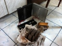
*****I dont have a problem with the heat disipation from the class A amp as i already have the radiators from below for the amp, and the small black radiator for this PSU (the one with TO-3 devices on it). I want to buy some aluminium fins (in plus) from the local vendor for the back side of the small black radiator.
I want to make two cap multipliers for a dual mono @30W class a (Hiraga or JLH biased at 1.5 amps@+-25Vcc). I already have a pack of 12 cm of E20 laminated cores ready for winding so the trafo and radiators are not a problem for me. The expensive and bulky capacitors are a real problem for me (and all class A builders i think) thats why i was hoping to get some help with this wonderfull cap multiplier.
If you want to redesign this cap multiplier for us (class A lovers) i think that you would do a big favor for the class A comunity and other builders as well.
Kind regards and thank you for the fast response.
Greater voltage drop across the pass transistor, in combination with higher continuous current, means much more heat. The 11 C/W rated heatsinks I am using are not going to be enough. I believe you will need 5-7 C/W rated heatsinks or better, because the inside of a class-A chassis is expected to be much warmer than class A-B.
*****I dont have a problem with the heat disipation from the class A amp as i already have the radiators from below for the amp, and the small black radiator for this PSU (the one with TO-3 devices on it). I want to buy some aluminium fins (in plus) from the local vendor for the back side of the small black radiator.
I want to make two cap multipliers for a dual mono @30W class a (Hiraga or JLH biased at 1.5 amps@+-25Vcc). I already have a pack of 12 cm of E20 laminated cores ready for winding so the trafo and radiators are not a problem for me. The expensive and bulky capacitors are a real problem for me (and all class A builders i think) thats why i was hoping to get some help with this wonderfull cap multiplier.
If you want to redesign this cap multiplier for us (class A lovers) i think that you would do a big favor for the class A comunity and other builders as well.
Kind regards and thank you for the fast response.
Attachments
I don't think 1.5A continuous is a problem, you can probably use it as is. I am still looking into various options for continuous power operation, so I will do a little testing and investigation with that in mind, but I have already run at higher current just fine.....a dual mono @30W class a (Hiraga or JLH biased at 1.5 amps@+-25Vcc)...
If I were you, I would still discuss it a bit with other people who are building similar amplifiers before you commit to it. There may be other requirements I am not aware of.
3V Vin-Vout for 1.2A bias total per polarity work stably in the common between channels cap multiplier that I have shown for TSSA 1.6 Class A CFA amp. That is enough to take its power transistors sink 20C above ambient and the TO-220 diodes sink too. One sink caters for both polarities. Working in moderate distance between hot flanking Class A amp sinks is a factor of course. Check out the sinks used for that Cmult
Thanks! What kind of diodes, if I may ask? And, if you have anything else to contribute for the guys contemplating class-A use, please do, ...🙂3V Vin-Vout for 1.2A bias total per polarity work stably in the common between channels cap multiplier that I have shown for TSSA 1.6 Class A CFA amp. That is enough to take its power transistors sink 20C above ambient and the TO-220 diodes sink too. One sink caters for both polarities. Working in moderate distance between hot flanking Class A amp sinks is a factor of course. Check out the sinks used for that Cmult
For anyone else, Please note that those are much bigger heatsinks than I have specified for class A-B (but so are the ones shown by Sergiu). A 5V drop at >1A idle current is not advisable with my $1 heatsink. For that I suggest mounting the pass transistors (at least, and perhaps the diodes also), from below w. larger heatsink, as shown in the pics above, or something similar to that shown by Salas.
- Status
- Not open for further replies.
- Home
- Amplifiers
- Power Supplies
- Finished capacitance multiplier