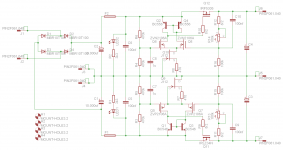
R11, R12 on your schematic should be 100k, not 8R2!
Yes right, thanks for pointing the mistake.
Marc
Last edited:
Should be fine. For higher voltages, the only thing that might cause problems is finding a JFET with suitable rating (in PMI's design, it needs to be able to handle 0.5x the input voltage, in my original design it's 1.5x).Mr. Evil,
I would like to use this cap multiplier circuit in following situation, do you see any reason's why it would not work:
Main xfmr r-core 500va 2x36v for OPS
A second xfmr r-core 30va 2x9v for front end drivers
For front end and drivers psu, the secondaries of both xfmr's will be in series.
I would like to use your cap multiplier (with higher voltage rating components) for the driver stage with an adjustable voltage drop to about 8v.
A second cap multiplier would be used for the front end with a voltage drop set at about 4v.
Greetz
Ben
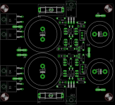
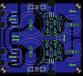
Looks nice Marc, like all your other layouts, 😉First layout try on PMI schematic...
Board size : 110x95mm with all devices on one heatsink. This board has less option as PMI one due the size goal
You are correct about the board size and options. I do have a comp placement & route that will work on one layer, but it looks like I have to extend the board another 5-10 mm to make sure it can be diy etched. I will try to get back to it later today.
J112 is rated at up to 35V breakdown voltage. Another alternative, BF244B, 30V (requires 390R instead of 470R).Should be fine. For higher voltages, the only thing that might cause problems is finding a JFET with suitable rating (in PMI's design, it needs to be able to handle 0.5x the input voltage, in my original design it's 1.5x).
I connected the Jfet to ground because I wanted to be able to run the supply up to +/-60V rails (eventually), and that was easier if the Jfet has to be rated at only 1/2 rail voltage.
The startup and shutdown may not be as smooth as the original circuit, but it is still quite good. Better than I had hoped frankly. I think this is a very clever and cool (pun intended) version of a Cap Multiplier circuit that MrEvil has gifted us with here.
I captured the startup traces on my old Tek digital memory scope, post #53, here:
Startup and Shutdown
There is a very small notch at around 2V in the rise curve, but this is at such low voltage it does not seem to cause any kind of sound from the speakers on startup.
Last edited:
Could be just about perfect for linear computer supplies
If anyone has a comment concerning use a replacement for an ATX supply I would be appreciative.
Previously used voltage regulators but worry that another voltage regulator is not what is needed here.
If anyone has a comment concerning use a replacement for an ATX supply I would be appreciative.
Previously used voltage regulators but worry that another voltage regulator is not what is needed here.
I would like to add my name to the list
IvanLukic(3)
Freeman(tbd)
Idefixes(tbd)
Touchdown(2)
vgeorge(2)
Jameshillj(2)
Jsixis(2)
Praudio(2)
Compressit(2)
Cambe(2)
Gannaji(1)
Potepuh(2)
Syklab(2)
quan(2)
tjencks(2)
BYRTT(4)
Ryssen(2)
rickmcinnis(3)
IvanLukic(3)
Freeman(tbd)
Idefixes(tbd)
Touchdown(2)
vgeorge(2)
Jameshillj(2)
Jsixis(2)
Praudio(2)
Compressit(2)
Cambe(2)
Gannaji(1)
Potepuh(2)
Syklab(2)
quan(2)
tjencks(2)
BYRTT(4)
Ryssen(2)
rickmcinnis(3)
ATX supplies can have very high and continuous output currents, and this translates into heat that has to be dissipated in the pass transistor heatsink in a Cap Multiplier.If anyone has a comment concerning use a replacement for an ATX supply I would be appreciative.
Previously used voltage regulators but worry that another voltage regulator is not what is needed here.
PC supplies normally also require good voltage regulation. Here the voltage will vary with normal line and load changes. In other words, the filter dropout voltage is regulated, but the output voltage will still vary as a function of line voltage, and load regulation at the transformer.
I figure the MB regulators will do just fine
The voltage could not vary that much.
Yes, I know the pass element will have to be heat sinked properly.
My set-up only requires around 1A average on the 5 volts rail so this should be simple for your CM.
Worth a try, I think ...
Thanks very much for your comment.
The voltage could not vary that much.
Yes, I know the pass element will have to be heat sinked properly.
My set-up only requires around 1A average on the 5 volts rail so this should be simple for your CM.
Worth a try, I think ...
Thanks very much for your comment.
First layout try on PMI schematic...
Board size : 110x95mm with all devices on one heatsink. This board has less option as PMI one due the size goal
Hi Idefixes,
Nice layout 🙂
A couple of points that may be worth noting (or not, I'm not an expert).😀
Eagle can now connect 1 pin to 2 pads so you don't need to do that trick on the schematic to connect both pads together. See the standard library: con-faston, device: PIN2 for an example on how to create the component.
It is advisable to use a vector font on Eagle PCBs. The text will move around when you generate your gerbers otherwise.
You may need to add larger holes to allow the head of the bolts to go through the PCB on the transistors on the heatsink.
It is nice and less error prone to have all the polarised capacitors orientated in the same direction.
For standard resistors I usually allow 10mm. They will squeeze into 7.5mm but don't look as nice.
A shorted legged version of the component for Q11 and Q12 will fit nicer.
regards
In that case, yes. I just wanted to make sure you knew what you were getting... 😉...My set-up only requires around 1A average on the 5 volts rail...
Hi Idefixes,
Nice layout 🙂
A couple of points that may be worth noting (or not, I'm not an expert).😀
Eagle can now connect 1 pin to 2 pads so you don't need to do that trick on the schematic to connect both pads together. See the standard library: con-faston, device: PIN2 for an example on how to create the component.
It is advisable to use a vector font on Eagle PCBs. The text will move around when you generate your gerbers otherwise.
I will look that
You may need to add larger holes to allow the head of the bolts to go through the PCB on the transistors on the heatsink.
Generally i drill 8mm hole for this use and it fit.
It is nice and less error prone to have all the polarised capacitors orientated in the same direction.
Yes it's what i make , but i this case the caps orientation allow to place faston spad either over nor under caps... i will check what i can achieve
For standard resistors I usually allow 10mm. They will squeeze into 7.5mm but don't look as nice.
I use 207/7 package in general because of place saving, and 207/10 when i need to route more than 2 tracks between res. pads. When you check the layout with 207/10 at every place i have to grown the size board and 110*95 may be 100mm is the max i can. I agree nothing impossible to do for swap to 207/10 in this particular layout but with others it's critical...
A shorted legged version of the component for Q11 and Q12 will fit nicer.
regards
I will try, bu need to create package i think...
Thanks for spended time to advice me.
Marc
Please add me to the list.
IvanLukic(3)
Freeman(tbd)
Idefixes(tbd)
Touchdown(2)
vgeorge(2)
Jameshillj(2)
Jsixis(2)
Praudio(2)
Compressit(2)
Cambe(2)
Gannaji(1)
Potepuh(2)
Syklab(2)
quan(2)
tjencks(2)
BYRTT(4)
Ryssen(2)
rickmcinnis(3)
still4given(4)
IvanLukic(3)
Freeman(tbd)
Idefixes(tbd)
Touchdown(2)
vgeorge(2)
Jameshillj(2)
Jsixis(2)
Praudio(2)
Compressit(2)
Cambe(2)
Gannaji(1)
Potepuh(2)
Syklab(2)
quan(2)
tjencks(2)
BYRTT(4)
Ryssen(2)
rickmcinnis(3)
still4given(4)
Since there are still names being added to the list, I am going to split the order into two parts.
This way, I can get boards into the hands of the first people who signed up earlier. At the same time, we will not be straining the limits of the discount we are using, which is intended for prototypes and very small lots, and it will make it easier to reorder if there is any interest in the future.
There are 2 boards left from the original batch.
Allowing for shipping from the board house to me, the second lot will be in my hands Tue-Wed of next week.
The third one a few days after that.
The J112 Jfet seems to cost up to 50 cents each (from Digikey), but only 10 cents in q. 100, so I plan to include a couple of those with every board, at least for those whose names are on the list as of now.
PMI,
The list is not yet updated with two pcbs for Joachim Gerhard. That would be 41 pcbs excluding Freeman and Idefixes.
The list is not yet updated with two pcbs for Joachim Gerhard. That would be 41 pcbs excluding Freeman and Idefixes.
The J112 Jfet seems to cost up to 50 cents each (from Digikey), but only 10 cents in q. 100, so I plan to include a couple of those with every board, at least for those whose names are on the list as of now.
I found them here in Serbia at 1,20 dollars each! It is the most difficult part to find so your decision to buy 100 is much appreciated and very helpful.
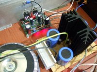
ATX supplies can have very high and continuous output currents, and this translates into heat that has to be dissipated in the pass transistor heatsink in a Cap Multiplier.
Indeed. This size a sink reaches almost 20C above ambient at 7W constant loss. Its for a multiplier (Darlington) serving a two channel class A amp.
Attachments
- Status
- Not open for further replies.
- Home
- Amplifiers
- Power Supplies
- Finished capacitance multiplier