Once, if you corrected the natural responses to flat (not so hard with DSP), you don't need to customize and modell the Q-s of the crossover filters and you can easily experiment with different slopes/points just by applying textbook crossover filters. The drawback is that it usually (but not always) takes more resource from the DSP.
Hi YSDR, I like to take the minimal approach. Admittedly I have not done DSP work before, but IMO not brute forcing the driver to do something it normally wouldn't should result in more natural sound. I could of course be completely wrong on that 🙂
I'm interested to try the IIR on my MTM measurements I have. Those I have full horizontal polars through 180 deg. Getting drivers flat before applying crossovers will make them flat on ONE axis only, how they behave off axis could be really ugly. I'm curious to see.
Tony.
I'm interested to try the IIR on my MTM measurements I have. Those I have full horizontal polars through 180 deg. Getting drivers flat before applying crossovers will make them flat on ONE axis only, how they behave off axis could be really ugly. I'm curious to see.
Tony.
Hi!
I didn't said that brute forcing is the only way to go. If we apply the crossover filters the forcing would go away if the slopes/points are not too wild. Yeah, flattening is just one method and I think it's interesting to try out once if possible, just out of curiosity. Why not?
Sure, it's one (main) axis only.
As for the responses, the result would be the same for an LR2 and an LR4 with regards to the inter-driver phase differences that were present before applying the filters, but the overlap will be different.We don't know yet how the phases matches to each other, might be a strange luck with the LR2 to ended up with a better combined frequency response.
Hi YSDR, my comments were pure opinion based on ZERO experience with DSP's 😉 so can be taken with a large grain of salt.
There are indeed many ways to get an acceptable result in the end what works for you is the important bit 🙂 This was my first time playing with IIR's in a sim, using the filter blocks I did as far as I can see it is fairly limited (at least in vituix cad) as only the 2nd order generic filter allows Q adjustment (I guess that makes sense as the others if name LR or Bessel, or whatever need to actually be that electrically).
To get really custom results would require cascading of the filter blocks (and that is limited as well). This is probably more work than a lot of people would want to do.
I just approached it the same way I would for a passive crossover, find a filter transfer function that molds the drivers response to an acoustic target, but what I did may not be appropriate in a lot of situations.
Tony.
When you know passive, much about using digital filters is obvious. IIR in VCad are the same as passive filters. One thing I found out is that some DSP implementations offer driver flattening routines, which confirms my suspicion that it is a convenience feature. Accepting this convenience gives up accounting for system idiosynchrasies that are not part of a given response. JohnK has just said here..I just approached it the same way I would for a passive crossover, find a filter transfer function that molds the drivers response to an acoustic target,
john k... said:You don't flatten first and apply a filter. You design the filter to do what you want.
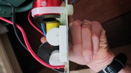
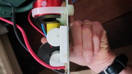
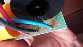
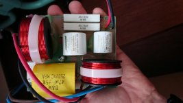
I don't know what you've done but those didn't come through as expected. Did you use the [Manage Attachments] control below submit reply?Here are the original mf hf photos.
looking some more, this post by john k explains the limitations I was seeing with the IIR blocks.
Tony.
If you use IIR you are limited to cascading minimum phase filters and drivers. You can not, for example, achieve an acoustic LR4 LP on a midrange driver. But with FIR you can define the acoustic target to be a minimum phase LR4 response and construct an FIR filter that, when cascaded with the driver's response, will yield an LR4 acoustic response.
I think that is the difference. With FIR you can design the filter to provide what ever acoustic output (target) you like. With IIR you are just cascading biquad stages with varying Q along with biquad notch, peak, shelf stages to get the best match to the target you can.
Tony.
All John is saying is that when using traditional filters, the phase takes shape according to the response. There is another kind of filter (FIR) that takes a more theoretical approach and can force phase and response independently.
In the bigger picture though, that thread is questioning the benefit of arbitrary phase in the context of someone wanting to make a flat system, and seems to be concluding that it is not as big a deal as the attention it receives.
In the bigger picture though, that thread is questioning the benefit of arbitrary phase in the context of someone wanting to make a flat system, and seems to be concluding that it is not as big a deal as the attention it receives.
I interpreted it as it being difficult to produce an arbitrary transfer function with IIR but possible with FIR, sure the particular context is around minimum phase, but I guess more generally the arbitrary transfer functions is what interests me 🙂
Maybe I'm just a ludite, I developed my analog active crossover so I could use the same techniques as I do for passive, now I'm looking at this DSP fangled stuff and doing the same 😉 BUT it is because to me the workflow should basically be the same regardless of the means to realize it. ie work out an acoustic target that is hopefully going to meet your goals, and then design filters that will achieve that acoustic target.
I truly believe that ignoring this "acoustic target" part of the workflow will most of the time result in a speaker that does not reach the potential it actually could.
Tony.
What you say makes sense to me.
IIR is not a digital thing, passive crossovers are IIR. So the question for yourself can become: Do you feel it is difficult to produce an arbitrary transfer function when designing your crossovers now?as it being difficult to produce an arbitrary transfer function with IIR
I can't seem to upload te filter photo's due to permission problems. Strange, I'll try and use my computer when I get home.
And that last one that didn't work, was that the soldered side of the board, a most important one.
What you say makes sense to me.
IIR is not a digital thing, passive crossovers are IIR. So the question for yourself can become: Do you feel it is difficult to produce an arbitrary transfer function when designing your crossovers now?
Hmm, I guess the limitation I was seeing with vituixcad was that the only thing I had to work with (that was configurable any way other than changing corner frequency or order) was a 2nd order block where I could change the Q. That seemed pretty limiting. But this is my first look at any digital means of making crossovers, so I am basically very naive as to how they work. If I could do anything I could do with a normal passive filter with IIR then I guess it is not as limiting as what I was thinking. I guess the key was in what I said about cascading blocks. There are 1st order and 2nd order blocks so in reality any combination should be possible.
Tony.
- Home
- Loudspeakers
- Multi-Way
- Filter recommendation (using Hypex Software Design)


