Hello, probably a dumb question, what are the attributes of fitting a small value capacitor on the primary and secondary sides of a transformer used for a power supply for an audio amplifier. Any advice or thoughts welcome.
Thanks
Alan
Thanks
Alan
It was done frequently in the 60's and 70's, on the secondary. .01 uf 1000 v was a typical value. I presume this was done to suppress transient voltage that is quite common from AC motor shutoff and lightning strikes down the line.
More to the point these days are MOS AC voltage supressors, that have a defined AC rating, typically 150% of the normal AC line voltage. They also have defined energy they will supress to what clamp voltage. I've been putting these on transformer secondaries, since I noticed them on the input in AC driven variable frequency drives.
I've had power switches carbon tracked "on", and shut off pop filter disk caps across power switch vaporized, on days when lightning was prevalent.
These days X or Y rated capacitors should be used in this position since they are rated to fail "open" instead of short. Which one, read the literature.
Last edited:
It's not unheard-of to see a capacitor connected directly across the secondary of a power transformer. My own personal taste is to use a 2C+1R snubber across the secondary instead. This variation completely eliminates oscillatory ringing of the RLC resonant circuit in the secondary, at the cost of an extra resistor and an extra capacitor. Some people like the idea, others do not.
_
_
As SY hinted, you need to know what the purpose is - what problem you are trying to solve.
A cap acrosss the primary (must be an X-rated cap) will reduce switch-off clicks and prolong the life of the switch. Don't be tempted to put the cap across the switch, although many people do.
A cap across the secondary will lower the frequency of ringing when the rectifiers switch off, and so reduce induction into nearby circuit loops. In conjunction with the secondary resistance it forms a crude snubber. Some people prefer a CR snubber.
Caps across the rectifiers are used in some radio receivers to stop modulation hum - caused by the diodes modulating stray RF from oscillators. Caps or snubbers are also used to deal with rectifier charge storage issues - but you can use better rectifiers instead.
thanks for the replies. I have seen power supply diagrams with capacitors fitted across the primary and across the secondary windings and I have also seen diagrams with no capacitors fitted. I would just like to know if they are beneficial or not, if they are deemed to be of use could values be suggested, also values of snubber resistor/cap.
I do not have a problem as such, just trying to gain more knowledge from experienced people to help me in my hobby.
Thanks
Alan
I do not have a problem as such, just trying to gain more knowledge from experienced people to help me in my hobby.
Thanks
Alan
Capacitors between lines can act as differential mode filters when the preceding impedance is included to give an LC filter.
These are often fitted to attenuate RF interference on the mains.
Some interference will get past the filter and into the transformer.
One could add a second stage of filtering after the transformer to further attenuate interference. Again one needs a combination of impedance and capacitance to create the filtering effect.
One can also filter common mode interference from line to enclosure.
The differential and common mode filters are the X & Y capacitors inside a mains interference filter can. Typical are the filtered IEC socket cans.
Last edited:
Noisy power mains are hit and miss, I have used the same parts inside a steel cased power strip with varying results depending on the particular household or amp/setup.
These parts are as described in the previous post, and in my case are two chokes and three X capacitors. If you search for Shunyata DIY, you will find some info on how to simply replicate a fairly expensive power strip.
These parts are as described in the previous post, and in my case are two chokes and three X capacitors. If you search for Shunyata DIY, you will find some info on how to simply replicate a fairly expensive power strip.
I don't think power strip filters or IEC socket filters are intended to filter mains noise entering the devices connected. They are widely deployed on commercial computer systems, PCs and SMPS devices generally, with the purpose of keeping digital hash and HF switching noise out of the local mains supply but not necessarily to prevent wideband noise getting into the device. Hence the filter's metal shield and a general requirement for full metal enclosures there.Noisy power mains are hit and miss, I have used the same parts inside a steel cased power strip with varying results depending on the particular household or amp/setup......
The hit and miss experience is probably the same everywhere they are used on the presumption they are wideband line filters.
I don't think power strip filters or IEC socket filters are intended to filter mains noise entering the devices connected. They are widely deployed on commercial computer systems, PCs and SMPS devices generally, with the purpose of keeping digital hash and HF switching noise out of the local mains supply but not necessarily to prevent wideband noise getting into the device. Hence the filter's metal shield and a general requirement for full metal enclosures there.
The hit and miss experience is probably the same everywhere they are used on the presumption they are wideband line filters.
Yep, not critical for audio but critical for manufacturing process where we use dedicated main power supply filtering modules which isolate the line from the power transformer of the relays&controls, computer chips
I must be imagining things again then, I hate it when that happens.
I can really notice it on my headphone setup. That and some of our instrumentation here at work.
I can really notice it on my headphone setup. That and some of our instrumentation here at work.
Instrumentation power supply rule & Dwarf anything audio related with the big margins of profit to fuel marketing.
Marketing? I guess I don't understand your comment. I am not using off the shelf iec sockets either, sorry if that was assumed to be the case. On large amps, where there is more space, I will build the differential mode filter inside the amp chassis.
I have witnessed faster settling times and less dithering while using sensitive equipment while on the improved power strip.
Murata has some good info on differential mode noise that you can read up on, technical write ups, not a marketing brochure, just so you understand.
If you are happy with what you currently have, and don't want to improve it then keep doing the same thing you always have, is largely human nature really.
BTW, this thread should be in the power supply section.
It should be in the power supply section!
I said that I find industrial power supply extremely good and dwarf any audio amp power supply.
My only explanation is that in audio there is a good margin to make adds, while for industry there is marketing but not so much.
I said that I find industrial power supply extremely good and dwarf any audio amp power supply.
My only explanation is that in audio there is a good margin to make adds, while for industry there is marketing but not so much.
Yes, the industrial, (and medical equipment too)is pretty well made compared to our recreational gear.
And when I say hit and miss, my father made a filter power strip or whatever and it made no difference, he also lives next to a mini sub station full of capacitors the size of car batteries.
The way to tell is to try one X type cap across incoming ac and see if there is any difference.
And when I say hit and miss, my father made a filter power strip or whatever and it made no difference, he also lives next to a mini sub station full of capacitors the size of car batteries.
The way to tell is to try one X type cap across incoming ac and see if there is any difference.
(...)A cap acrosss the primary (must be an X-rated cap) will reduce switch-off clicks and prolong the life of the switch. Don't be tempted to put the cap across the switch, although many people do.(...)
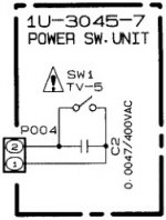
I agree with this advice from DF96, and have been wondering why an X-cap across the mains switch actually seems to be standard in commercial Hi-Fi gear. In almost every amplifier I have looked at, there is a 0.0047 or 0.01mF right across the switch. See attached example taken from a Denon schematic. All the major brands I have seen, do the same thing. If the cap was combined with a resistor, to make a arc-reducing snubber, it would make sense, but it is just the X-type cap.
Does anyone have an explanation for this practice? Why don't they instead place the cap between the phase and neutral AC leads after the switch?
Attachments
I agree with this advice from DF96, and have been wondering why an X-cap across the mains switch actually seems to be standard in commercial Hi-Fi gear. In almost every amplifier I have looked at, there is a 0.0047 or 0.01mF right across the switch. See attached example taken from a Denon schematic. All the major brands I have seen, do the same thing. If the cap was combined with a resistor, to make a arc-reducing snubber, it would make sense, but it is just the X-type cap.
Does anyone have an explanation for this practice? Why don't they instead place the cap between the phase and neutral AC leads after the switch?
Contact arc suppression versus snubbing of the transformer primary perhaps?
Even with a completely resistive load, a switch can arc when its contacts are opened or closed. The switch is connecting and disconnecting over the full mains or other voltage that it is controlling. The contacts may bounce, too. The purpose of the parallel cap is likely to address this issue.
When the load is inductive (like the transformer primary) there will also be flyback when the switch is opened (at turn off). An RC snubber in parallel with the primary could address this. I'm not sure but one on the secondary might also do that via the magnetic coupling of the transformer (if that is the inductive load).
Some people believe that a capacitor across the terminals of a switch will prolong the life of the switch. They feel that since the switch can open (or close) at any and every possible phase angle of the mains waveform, one fine day it eventually will open (or close) at the very worst case phase angle -- the one that injures the switch most.
Contact arc suppression versus snubbing of the transformer primary perhaps? (...)
Yes the cap across the switch can only be for arc suppression - which we shouldn't confuse with transformer snubbing or RF filtering. But as far as I know, to do a proper arc suppresion, just a cap is insufficient. It must be in series with a resistor, and the values should be calculated for the expected load on the switch. There are devices made specifically for this purpose, usually called "spark quenchers", where this R-C network is combined in one package.
So I find it puzzling that it is so common to just fit a cap, and also that is it placed across the switch, instead of after the switch between hot and neutral. Some of the most experienced users here, have argued convincingly (also in another thread on this issue) that it is bad practice to fit it across the switch due to safety reasons - even when it is an X-type.
- Yes, but not just "some people", it seems that the engineers at all the major Hi-Fi brands agree on this! - which makes me think that perhaps they are right somehow - I mean, there must be some smart people designing at Denon, Luxman, NAD etc..Some people believe that a capacitor across the terminals of a switch will prolong the life of the switch. (...)
-Or perhaps it just a simple cost savings thing? They save a few cents by skipping the resistor, since arcing on the switch is not really an issue on regular amps, and fit just a cap for "tradition"?
Hi CharlieLaub, I just found a thread from 2012, where you have posed a very similar question:
"I have some schematics for commercial amps, and these show a 10nF (0.01uF) X2 "safety" cap in parallel with the live wire switch contacts. I did some reading about snubbers for arc suppression, but was surprised to see commercial designs only using a single cap (which I assume is for suppressing the pop that I am hearing). Usually the manufacturers don't put in extra components that aren't needed, so I am guessing that the single X2 cap on the mains switch works."
(from arcing mains switch -> add cap in parallel -> WHY?)
🙂
- Status
- Not open for further replies.
- Home
- Amplifiers
- Solid State
- Film capacitors on AC