A cap across the transformer primary (after the switch) works just as well as a switch arc suppressor as a cap across the switch. This is because the incoming mains supply has low impedance and the 115V/230V is small compared to the back EMF caused by breaking the circuit. Hence in either position the cap reduces the back EMF when stored magnetic kinetic energy is converted into potential energy across the cap.
Putting the cap across the switch means that 'off' no longer means Off. For domestic equipment, which will be 'off' most of the time, it shortens the life of the cap. For equipment which is likely to be 'on' most of the time then the cap can be across the switch so the cap is usually shorted.
Using a cap without a resistor just means that the transformer resistance is used to damp the oscillation. This is good enough to protect the switch. The use of a snubber on the secondary to damp ringing there is a different solution to a different problem - although even there just a cap may be good enough.
Putting the cap across the switch means that 'off' no longer means Off.
Quite apart from the other points DF96 makes, this is a serious point: on 240VAC, a 100nf cap as originally suggested as a snubber illustrated across the switch is feeding c. 7.5 mA into the 'isolated' circuit.
That is quite capable of being fatal to the uninformed servicing/fiddling with it internally, and wastes power, and not a good idea at all.
It could perhaps be argued that a cap across the switch compromises safety so should be a Y-rated cap - which also means a smaller cap value. 10nF would still protect the switch from arcing.
Hi CharlieLaub, I just found a thread from 2012, where you have posed a very similar question:
"I have some schematics for commercial amps, and these show a 10nF (0.01uF) X2 "safety" cap in parallel with the live wire switch contacts. I did some reading about snubbers for arc suppression, but was surprised to see commercial designs only using a single cap (which I assume is for suppressing the pop that I am hearing). Usually the manufacturers don't put in extra components that aren't needed, so I am guessing that the single X2 cap on the mains switch works."
(from arcing mains switch -> add cap in parallel -> WHY?)
🙂
Yes, posts like these contain many of the answers you seek:
arcing mains switch -> add cap in parallel -> WHY?
arcing mains switch -> add cap in parallel -> WHY?
...and wastes power....
No, it is a reactive current, no power wasted at all. It flows out of phase respect to voltage. Only a minute power wasted in the resistive components atf the primary of the transformer and the eflected from the secondary.
Good plan to use a Y rated part, but I really don't think there will be much power lost there.
If there is, that's where the fire-rated part will be appreciated.
If there is, that's where the fire-rated part will be appreciated.
FWIW I have been placing a cap across the switch contacts for almost 50 years, and always substantially reduced switching pops heard through speaker.
Practically never ever used caps across primaries or secondaries, basically because never heard an , forgive the redundance, "audible" difference.
Not preaching or dissing, everybody is free to do what he prefers.
Practically never ever used caps across primaries or secondaries, basically because never heard an , forgive the redundance, "audible" difference.
Not preaching or dissing, everybody is free to do what he prefers.
It's often surprising how complicated the simple isues can get 🙂
After reading through the replies here, and in the older thread on the same topic, I believe the following is valid:
1. A small value X-cap (such as 10nF) across the mains switch is safe enough since all major commercial brands do it, and is a cheap and simple (albeit primitive) way to handle back EMF from transformer on turn-off, and prevent arching and reduce "popping" noise in speakers.
Quoting explanation by user "M Gregg" (from here):
"The idea is that any coil that has a magnetic field around it at power "Off"..the magnetic field collapses..This then cuts though the windings creating a back EMF (Voltage sometimes very high 1000V or more) this tries to conduct if the switch is opening the gap acts as a spark plug (like in your car) and the voltage causes a circuit to form as it arcs across the gap in the switch...as the switch gap gets bigger (opens to full gap) the arc is drawn wider until it cannot conduct any more or runs out of generated EMF and stops..
The cap across the switch acts as a temporary short (probably better to say it absorbs the energy) as the contacts open long enough for the gap to get to big for the arc to happen..
The comercial designs get away with this...its cheap...the answer is to stop the EMF at source using MOV protection and the cap...Why you may ask...well if the voltage from the EMF is higher than your transformer insulation can take, it will arc between the windings and stuff it..Also the switch can weld closed with inrush current so surge protection can reduce the inital current flow as the caps charge on power up..so you have to protect on power on and off..."
2. A better solution to back-EMF and switch arching, is a properly designed network across the primaries (after the switch).
There is more than one way of doing this, but a cap+resistor in series (RC snubber), perhaps combined with a MOV in parallel should work well. With this solution, there is no need (or point) of the cap across the switch.
A cap across the switch or a cap across the primary do almost exactly the same job: suppress switch arcing. No need for both. The difference you may hear is no 'pop' on switch off. Secondary caps do something different.JMFahey said:FWIW I have been placing a cap across the switch contacts for almost 50 years, and always substantially reduced switching pops heard through speaker.
Practically never ever used caps across primaries or secondaries, basically because never heard an , forgive the redundance, "audible" difference.
As I said, the kinetic energy in the transformer is transformed into potential energy across the circuit capacitance. The cap does not act as a short, but as a capacitor. The bigger the cap the smaller the voltage. You just need a cap big enough to keep the voltage low enough as the switch opens.The cap across the switch acts as a temporary short (probably better to say it absorbs the energy) as the contacts open long enough for the gap to get to big for the arc to happen..
"perhaps combined with a MOV in parallel should work well. With this solution"
MOVs wear out and fail as a short circuit so don't use MOVs in a circuit without a fuse.
MOVs wear out and fail as a short circuit so don't use MOVs in a circuit without a fuse.
A cap across the switch or a cap across the primary do almost exactly the same job: suppress switch arcing. No need for both. (...)
I have no argument against this, which again brings me back to the question of why commercial audio consumer gear, seems to always have the cap across the switch..
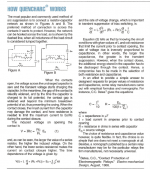
Also I found a short guide from Illinois capacitor that illustrates the principle, and also gives a formula to calculate values for an effective switch arc RC snubber. See attached..
Attachments
I suspect that if the capacitor is not too large (i.e. the current/power being switched is not too large) then there is no need for a resistor to limit contact current on switching on. Also, mains switches may be more robust than some relay contacts.
People may put the cap across the switch because of a gut feeling that this is where it should be. Makers of X caps do not usually advertise the fact that the self-healing property of the caps also means a self-degradation: every mains spike reduces the capacitance by a small amount. After 5 years of continuous operation the capacitance may have more than halved.
People may put the cap across the switch because of a gut feeling that this is where it should be. Makers of X caps do not usually advertise the fact that the self-healing property of the caps also means a self-degradation: every mains spike reduces the capacitance by a small amount. After 5 years of continuous operation the capacitance may have more than halved.
- Status
- Not open for further replies.
- Home
- Amplifiers
- Solid State
- Film capacitors on AC