Hi namghiwook,
Nice work! Looks like it’s working and no smoke so that’s great.
Post 811
https://www.diyaudio.com/community/...w-class-ab-for-lean-times.353512/post-6679388
Use mV mode on DMM. Measure across the big 0.22R 5W source resistors on the output.
Then slowly adjust the trimpot to control the bias current. Look for about 26mV. Doesn’t have to be exact. This lets the amp run in Class A for low power where you mostly listen. It will smooth out the sound.
Good luck!
@namghiwook
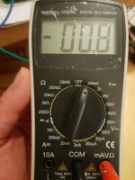
On your DMM, turn your dial until it points to the “200mV” setting not the “20mA” setting and again do the same measurement. Assuming that your blue potentiometer on the main FH9HVX board is oriented correctly, and completely turned counterclockwise, start to turn the pot ‘clockwise.’ Keep turning the pot a 1/4 to 1/2 turn at a time until you see a change on the DMM. Do it slowly and take your time.
Assuming you used 0.22 ohms for your current source resistors then use V= IR to calculate the quiescent bias current. Start at 80mA. So that means V = 0.08A * 0.22 ohms = ~18mV on your DMM
For 160mA (which is where most folks are setting the bias), that would be 36mV. X’s advice to set it at 26mV(~118mA) is also good advice. You can judge the sound at all these bias points and pick the one that you like the best.
Congratulations on your build.
Best,
Anand.
Last edited:

I've adjust the R124 trimpot to 500ohms (half value of 1kohms) before installation.
The value of R133 resistor is 0.22ohms.
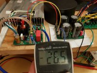
I connected the amp with a shorted input RCA and a real speaker.
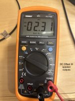
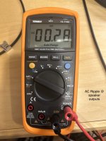
I adjusted the dial to 200mV range of the DMM and checked the bias with test points (x1031 - x1032 and x1033 - x1034).
The DMM read -00.3 <- minus value
I turned the trimpot clockwise about 3 turns and the DMM read -00.8
I felt something was wrong then stopped it all.

The value of R133 resistor is 0.22ohms.
I connected the amp with a shorted input RCA and a real speaker.
I adjusted the dial to 200mV range of the DMM and checked the bias with test points (x1031 - x1032 and x1033 - x1034).
The DMM read -00.3 <- minus value
I turned the trimpot clockwise about 3 turns and the DMM read -00.8
I felt something was wrong then stopped it all.
Attachments
Last edited:
If the scale is 200mV then 0.8 means 0.8mV. I think you want about 20mV to 26mV. You can check this by putting it in plain V mode and see if it reads 0.8V. That would be 800mV and bad (the resistor would be smoking).
I personally think you are getting 0.8mV.
Keep turning it to get about 20mV. Look for heat and smoke as you turn it and go slowly. Shut off main power of you smell smoke, hear something burning or popping etc.
I personally think you are getting 0.8mV.
Keep turning it to get about 20mV. Look for heat and smoke as you turn it and go slowly. Shut off main power of you smell smoke, hear something burning or popping etc.
@namghiwook
I agree with X.
Also, if you don’t want the (-) number just switch the leads, then it will read + 0.8mV. Keep turning it slowly clockwise and the vBe multiplier circuit should kick in as the bias current increases.
You also don’t need a speaker connected to the output when adjusting bias.
Best,
Anand.
Attachments
Great news. Looks like you have a fully functioning amp. Please connect to a speaker and source and enjoy the fruits of your labor.
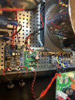
Yesterday, I connected both channels with 8ohms speakers and listened 4 or 5 songs without any problem.
But today when I connected this amp with my soundartist LS3/5a (11ohms), there were smoke and popping sound on the speaker .. so I turned it off immediately.
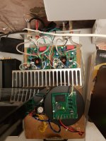
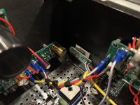
The current source resistors seemed to be burnt. I could see cracks on them... so I changed resistors with new ones.
... and I powered it up again with a dim blub tester, but it stayed on brightly.
I found that the leads of both N and P mosfets of 'the' channel amp are shorted and mosfets seems to be destroyed.
Question:
The impedance of speaker is concerning issue?
But today when I connected this amp with my soundartist LS3/5a (11ohms), there were smoke and popping sound on the speaker .. so I turned it off immediately.
The current source resistors seemed to be burnt. I could see cracks on them... so I changed resistors with new ones.
... and I powered it up again with a dim blub tester, but it stayed on brightly.
I found that the leads of both N and P mosfets of 'the' channel amp are shorted and mosfets seems to be destroyed.
Question:
The impedance of speaker is concerning issue?
Attachments

@namghiwook
No, your impedance is not the issue (unless your impedance is less than 1 ohm). The issue is that in your build, you must of missed something and your OUTPUT was accidentally connected to ground. So the amplifier was driving a direct short (~ 0 ohms) or close to a dead short. The amplifier continues to send too much current and burns up the current source resistors (0.22 ohms in this build) in the process because the amp operates open loop and each MOSFET takes turns trying to drive a 0 ohm impedance load. In the process they burn up the current source resistors which act like fuses.
This can happen for a number of reasons.
First, get new MOSFETS and new current source resistors. Turn the pot several times counterclockwise to set it back to the original setting because when you install the new MOSFETS you have to redo the biasing.
When you install the new MOSFETS, make 100% sure that none of the leads (Gate, Source, Drain) are connected to chassis ground.
You must use an insulation pad or aluminum oxide pad or mica between the MOSFET and the heatsink. I cannot see it in your latest picture, but in your previous picture it appears you have something like Keratherm.
I always rub a little sandpaper on the back of the MOSFET to remove any metal bristles so that it doesn’t pierce through mica or insulation pads like Keratherm. Little metal bristles will pierce through the Keratherm or mica and cause a short with the heatsink.For mica and aluminum oxide, always use heatsink grease. It’s not recommended for Keratherm or equivalents…
The back of the MOSFET is connected to the Drain lead so you can accidentally cause a short. All the leads from the MOSFET (when using the multimeter and connecting to chassis ground and to each other) should measure in the MEGAOHMS, not less than 100 ohms. If it is less than 100 ohms you have a short somewhere and/or dead MOSFETS or both. Investing in a transistor tester is useful. You can then test a MOSFET that you suspect is fake or damaged.
Use your DMM and connect one lead to the OUTPUT of your FH9HVX board. With the other lead of the DMM connect it to ground. Is there continuity? If there is, then you have a short. Find the short. Sometimes it is the binding post panel, sometimes it’s a PCB mounting hole (!!), sometimes it’s the mounting hole for the MOSFET itself, sometimes it’s because you failed to insulate the back of the MOSFET from heatsink, etc..etc…
Make sure V+/V-/G on the FH9HVX board are not connected to each other.
Best,
Anand.
Last edited:
@poseidonsvoice
Thank you for long and kind explanation.
I used 'used' Keratherm insulators, I know that Keratherm is so fragile, especially 'used' one .. so I checked no-continuity of all leads of mosfets and heatsink with DMM after fastening. I convinced there were no shorts anywhere.
At next time, I will make it with aluminum oxide ceramic insulators https://www.mouser.kr/ProductDetail/?qs=2v7q0MSBcBMwt5GBytMENg==
@namghiwook
Looking back at your build I did notice something.
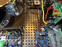
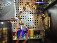
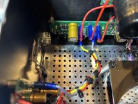
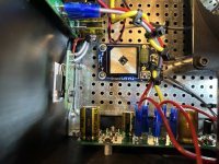
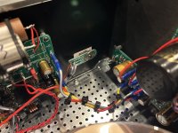
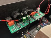
Both of your N channel and P channel Mosfets which appear to be nicely wired and do have insulation pads are mounted to the heatsink. But there is a problem. You have long lead wires going from the main PCB to your Mosfets. And your Mosfets are not connected to a ‘snubber’ circuit to deal with oscillation issues that can occur with long lead wiring. You need to be careful about this. This is bad practice.
Either attach the MOSFETS directly to the heatsink and hence directly to the main amp pcb or use a snubber circuit along with your longer leads.
The pcb snubber circuit is here: https://www.etsy.com/listing/766648...95&click_sum=6891b22e&ref=shop_home_active_22
You can probably ask X what the values are, or look at the circuit drawing here: https://www.diyaudio.com/community/...-8ohm-class-a-amp.344540/page-96#post-6839191; the same values work with either Alpha Nirvana or FH9HVX.
The other place where the Mosfet snubber is explained is the Alpha Nirvana GROUP BUY thread here:
https://www.diyaudio.com/community/threads/alpha-nirvana-39w-se-class-a-amplifier-gb.346033/
Pay close attention to the orientation of the Zener diode on the snubber board. It’s different depending on whether the board is being used with N-channel MOSFET vs P-channel MOSFET. There are plenty of pictures online to show this and on XRK’s etsy site.
The location of where to mount the MOSFETS on a heatsink is an option with the FH9HVX (unlike the Alpha Nirvana which is only Class A and runs much hotter). Most builders will mount the MOSFETS directly to the main pcb and directly to the heatsink without any long lead wiring, so no need for a snubber circuit.
But for others…the Mosfet snubber is the best option to eliminate oscillation risks.
Best,
Anand.
Looking back at your build I did notice something.
Both of your N channel and P channel Mosfets which appear to be nicely wired and do have insulation pads are mounted to the heatsink. But there is a problem. You have long lead wires going from the main PCB to your Mosfets. And your Mosfets are not connected to a ‘snubber’ circuit to deal with oscillation issues that can occur with long lead wiring. You need to be careful about this. This is bad practice.
Either attach the MOSFETS directly to the heatsink and hence directly to the main amp pcb or use a snubber circuit along with your longer leads.
The pcb snubber circuit is here: https://www.etsy.com/listing/766648...95&click_sum=6891b22e&ref=shop_home_active_22
You can probably ask X what the values are, or look at the circuit drawing here: https://www.diyaudio.com/community/...-8ohm-class-a-amp.344540/page-96#post-6839191; the same values work with either Alpha Nirvana or FH9HVX.
The other place where the Mosfet snubber is explained is the Alpha Nirvana GROUP BUY thread here:
https://www.diyaudio.com/community/threads/alpha-nirvana-39w-se-class-a-amplifier-gb.346033/
Pay close attention to the orientation of the Zener diode on the snubber board. It’s different depending on whether the board is being used with N-channel MOSFET vs P-channel MOSFET. There are plenty of pictures online to show this and on XRK’s etsy site.
The location of where to mount the MOSFETS on a heatsink is an option with the FH9HVX (unlike the Alpha Nirvana which is only Class A and runs much hotter). Most builders will mount the MOSFETS directly to the main pcb and directly to the heatsink without any long lead wiring, so no need for a snubber circuit.
But for others…the Mosfet snubber is the best option to eliminate oscillation risks.
Best,
Anand.
Last edited:
@poseidonsvoice
Thank you!
I know the oscillation issue from the long flying leads.
When I put them in a new chassis, I will make the flying leads shortest as possible.
.... and I already purchased Alpha Nirvana PCBs.
Thank you again!
Thank you!
I know the oscillation issue from the long flying leads.
When I put them in a new chassis, I will make the flying leads shortest as possible.
.... and I already purchased Alpha Nirvana PCBs.
Thank you again!
Poseidon’s FH9HVX build
Introduction - What’s in a name?
From time to time I get folks who are totally confused by the naming convention of this amplifier. I admit, it’s a little confusing. The nomenclature harkens back to the FX-8 design originally by Mile Slavkovic who hails from Serbia, also known by his diyaudio moniker - Apex Audio. Mile has one of the longest running diyaudio threads right here. Member XRK971 (hereby referred to as ‘X’) had built a number of his designs dating back to almost a decade; but one that he repetitively returned to (in many different variations) was the FX-8 design. He wasn’t alone in his enthusiasm. Since 2016, it has been built by a great number of diyaudio members all across the globe and most of the reviews I have read were quite positive if not tickled by the sound.
The FX-8 and the FH9HVX have pretty much the same DNA except for the implementation of vertical MOSFETS instead of Laterals which also meant the need for a Vbe multiplier circuit in the FH9HVX. If you want to explore more, I would suggest you read X’s treatise on Mile’s tremendous contributions to solid state audio designs, right here. It’s a plethora of circuits, all solid state, from preamplifiers to amplifiers of various genres, input stages, VaS stages and topologies.
But why the freakazoid nomenclature though? It’s easy:
F = FET output stage design. This is to distinguish it from other large output transistors, such as BJT’s, etc…
H = HexFet or Vertical MOSFET (to distinguish it from Lateral Mosfets).
9 = The number of active transistor devices in this circuit.
HV = High Voltage. It distinguishes it from the FX8 which was originally slated for +/- 35V. This version is goosed up to +/- 55V max.
X = XRK971, the master of ceremonies for this thread!
I became interested in this design only in the past year and because I wanted to build a standard issue 3-4 stage Class AB discrete design. Lord knows I don’t need yet ANOTHER amplifier but as we all know, I have a strange affliction, I mean addiction. And so here we are.

Theory of operation
As I was perusing the big 100W Class AB amplifier thread linked above, I ran into this diagram which describes the design topology quite succinctly and elegantly:

Observe the change in absolute phase as the AC music signal traverses its way through the amplifier. This happens to be pretty basic and is a very frequently seen design topology in all of amplifier design starting from the differential input amplifier/LTP on the left and ending with a pair of N/P Mosfets comprising the push pull output stage (not shown clearly above, it comes after the push pull driver stage).
Ingredients
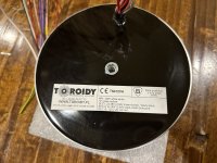
Toroidy 412VA w/quad 38V secondaries, and a single 12V/1A secondary
Softstart module w/Yakamoz latching push button switch
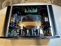
Dual Mono Power Supply composed of HexFred bridge rectification in a center tapped format with (4) 10mF Mundorf 4 pole capacitors
Hifisonix/Andrew Russell’s MRE (MicroRipple Eater) with Sanken transistors, one for each channel
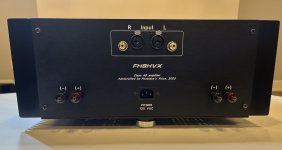
Panel Mount BTSB using Susumu resistors in the signal path as well as -6dB modification described here
AMB Sigma 25 w/Sigma 78 low noise voltage regulator supply boards
FH9HVX main board with Vcap ODAM/Miflex input capacitor, Takman metal film resistors, and Mills non inductive wirewound resistors, biased at 250mA/ch
MOSFET snubber boards using dual 18AWG wiring for Drain, single 18AWG for Source and single 22 AWG for Gate
Neurochrome Audio Guardian-86 speaker protect boards
Ground Lift circuit for main power supply
Composite Ground board
KLEI Classic Harmony Binding Posts
Furutech FI-06 IEC
Various gauge wiring (16AWG to 24AWG) from Neotech
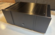
Customized Modushop 4U/300 Dissipante chassis
Introduction - What’s in a name?
From time to time I get folks who are totally confused by the naming convention of this amplifier. I admit, it’s a little confusing. The nomenclature harkens back to the FX-8 design originally by Mile Slavkovic who hails from Serbia, also known by his diyaudio moniker - Apex Audio. Mile has one of the longest running diyaudio threads right here. Member XRK971 (hereby referred to as ‘X’) had built a number of his designs dating back to almost a decade; but one that he repetitively returned to (in many different variations) was the FX-8 design. He wasn’t alone in his enthusiasm. Since 2016, it has been built by a great number of diyaudio members all across the globe and most of the reviews I have read were quite positive if not tickled by the sound.
The FX-8 and the FH9HVX have pretty much the same DNA except for the implementation of vertical MOSFETS instead of Laterals which also meant the need for a Vbe multiplier circuit in the FH9HVX. If you want to explore more, I would suggest you read X’s treatise on Mile’s tremendous contributions to solid state audio designs, right here. It’s a plethora of circuits, all solid state, from preamplifiers to amplifiers of various genres, input stages, VaS stages and topologies.
But why the freakazoid nomenclature though? It’s easy:
F = FET output stage design. This is to distinguish it from other large output transistors, such as BJT’s, etc…
H = HexFet or Vertical MOSFET (to distinguish it from Lateral Mosfets).
9 = The number of active transistor devices in this circuit.
HV = High Voltage. It distinguishes it from the FX8 which was originally slated for +/- 35V. This version is goosed up to +/- 55V max.
X = XRK971, the master of ceremonies for this thread!
I became interested in this design only in the past year and because I wanted to build a standard issue 3-4 stage Class AB discrete design. Lord knows I don’t need yet ANOTHER amplifier but as we all know, I have a strange affliction, I mean addiction. And so here we are.
Theory of operation
As I was perusing the big 100W Class AB amplifier thread linked above, I ran into this diagram which describes the design topology quite succinctly and elegantly:
Observe the change in absolute phase as the AC music signal traverses its way through the amplifier. This happens to be pretty basic and is a very frequently seen design topology in all of amplifier design starting from the differential input amplifier/LTP on the left and ending with a pair of N/P Mosfets comprising the push pull output stage (not shown clearly above, it comes after the push pull driver stage).
Ingredients
Toroidy 412VA w/quad 38V secondaries, and a single 12V/1A secondary
Softstart module w/Yakamoz latching push button switch
Dual Mono Power Supply composed of HexFred bridge rectification in a center tapped format with (4) 10mF Mundorf 4 pole capacitors
Hifisonix/Andrew Russell’s MRE (MicroRipple Eater) with Sanken transistors, one for each channel
Panel Mount BTSB using Susumu resistors in the signal path as well as -6dB modification described here
AMB Sigma 25 w/Sigma 78 low noise voltage regulator supply boards
FH9HVX main board with Vcap ODAM/Miflex input capacitor, Takman metal film resistors, and Mills non inductive wirewound resistors, biased at 250mA/ch
MOSFET snubber boards using dual 18AWG wiring for Drain, single 18AWG for Source and single 22 AWG for Gate
Neurochrome Audio Guardian-86 speaker protect boards
Ground Lift circuit for main power supply
Composite Ground board
KLEI Classic Harmony Binding Posts
Furutech FI-06 IEC
Various gauge wiring (16AWG to 24AWG) from Neotech
Customized Modushop 4U/300 Dissipante chassis
Attachments

Last edited:
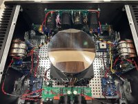
More pics attached…
Attachments
-
 IMG_9184.jpeg589.2 KB · Views: 278
 -
 IMG_9250.jpeg666.7 KB · Views: 267
 -
 IMG_9248.jpeg516.8 KB · Views: 250
 -
 IMG_9249.jpeg519.1 KB · Views: 264
 -
 IMG_9247.jpeg489.4 KB · Views: 261
 -
 IMG_9253.jpeg411.9 KB · Views: 256
 -
 IMG_9254.jpeg357.2 KB · Views: 280
 -
 IMG_9252.jpeg610.1 KB · Views: 276
 -
 IMG_9219.jpeg408.6 KB · Views: 278
 -
 IMG_9183.jpeg549.5 KB · Views: 286
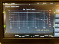
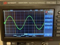
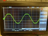
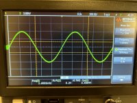
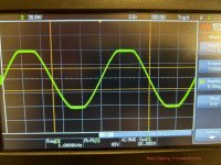
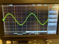
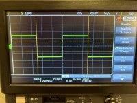
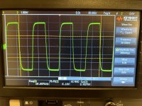
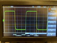
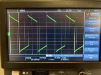
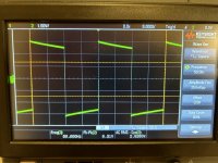
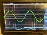
Measurements attached (remember my overall gain is only 24dB in my build, since I have implemented the -6dB option for the BTSB):
Attachments
-
 IMG_9230.jpeg567.3 KB · Views: 174
 -
 IMG_9188.jpeg396.7 KB · Views: 176
 -
 IMG_9187.jpeg420 KB · Views: 174
 -
 IMG_9245.jpeg529.4 KB · Views: 166
 -
 IMG_9244.jpeg516.6 KB · Views: 181
 -
 IMG_9236.jpeg526.5 KB · Views: 177
 -
 IMG_9234.jpeg488.2 KB · Views: 163
 -
 IMG_9243.jpeg502.5 KB · Views: 161
 -
 IMG_9237.jpeg497.4 KB · Views: 164
 -
 IMG_9242.jpeg533.4 KB · Views: 170
 -
 IMG_9241.jpeg492.3 KB · Views: 164
 -
 IMG_9240.jpeg538.2 KB · Views: 163
 -
 IMG_9239.jpeg514.9 KB · Views: 163
 -
 IMG_9233.jpeg478.9 KB · Views: 163
Sonic impressions forthcoming. I have several loudspeaker setups to evaluate this amp on which I will most likely compose and write up in about 1 month or so.
If any of you have questions/criticisms or need something clarified in my build, please let me know.
Best,
Anand.
If any of you have questions/criticisms or need something clarified in my build, please let me know.
Best,
Anand.
Superb FH9HVX Amplifier build Anand!!
Total package input to output and chassis, Just beautifully done!

PS, my 'plank' amp builds are just embarrassing
Total package input to output and chassis, Just beautifully done!
PS, my 'plank' amp builds are just embarrassing
Hi Anand,
Wonderful build and absolute attention to details. This really is as good as it gets I think. Congrats!
Looking forward to your listening impressions. Naming convention is spot on.
Wonderful build and absolute attention to details. This really is as good as it gets I think. Congrats!
Looking forward to your listening impressions. Naming convention is spot on.
- Home
- Group Buys
- FH9HVX - Budget Conscious 100w Class AB for Lean Times