Cool cool. Will the SSR board be available as a bare board, or will it have lots of small SMT components again?
SMT - it's the only way to keep it compact and cost effective. I might offer it as a bare PCB and you can do your own SMT soldering.
They are talking about thermistor between mains and SMPS. I am talking about in rush current from SMPS to the amp proper. Adding a hefty 47ohm (cold) thermistor between the SMPS and the amp will fix it - but the voltage drop across that is huge. A better alternative would be a SSR soft start between the SMPS and the amp. Or get a bigger SMPS.
In considering the Connex SMPS300REh for an amp build, I was thinking about this problem and actually sketched out a MOSFET circuit to limit the downstream inrush from the SMPS, then I realized the Soft as a Feather Pillow approach has solved this for AC. No reason it would not work for DC, correct?
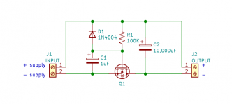
Anyway, I was thinking of something dirt-simple like the attached. The R and C values create a short time constant allowing the MOSFET to gradually ramp down to its lowest Rdson value, thus giving the SMPS time to start up. The MOSFET needs to be a device with very low Rdson, like ~ 1mOhm. The diode discharges the gate cap when the supply is shut down. Probably need a Zener across the gate cap as well to limit the gate voltage.
Attachments
Last edited:
Hi Wtnh,
That’s very nice. I was using the Juma Easy Peasy mosfet cap multiplier for this reason in the past - but always had a 3.5v to 4v drop. But if a low RDSon mosfet has low voltage drop, it might be perfect. I think Jhofland was making something like this to connect a SMPS to an amp.
Juma's Easy-Peasy Capacitance Multiplier
There are many decent low Rdson candidates these days. One example - not too costly - is the Infineon IPP032N06N3GXKSA1. About $1.76US in singles from Mouser.
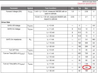
Rdson is about 2.5 mOhm with Vgs ~10 Volts, which would be fine for mid-voltage supplies up to 60 Volts.
You could use it with lower voltages (like with 5 Volt supplies), but Rdson rises to about 5 mOhm - not an issue for moderate loads. (5 mOhm is about what you get with 1 foot of 16 AWG wire).
It can handle up to 120 Amps!
There are other suggestions in the "perfect" rectifier threads.
Just thought I would pop back in to say that this amps gets even better with time. The one advantage of having it at work is that it plays near continuously while I am in my office (sadly close to 10 hours a day) and I just leave it all powered up all the time.
I thought it was my imagination but it definitely has more sparkle and nuance. Today was the second time that I was drawn out of my focus at work to listen to the music (probably not great for productivity but perfect for mental wellness)
Loving it.. dB
I thought it was my imagination but it definitely has more sparkle and nuance. Today was the second time that I was drawn out of my focus at work to listen to the music (probably not great for productivity but perfect for mental wellness)
Loving it.. dB
dBel84,
I am sure you know that mental wellness leads to better productivity! 🙂
Good to know that you are enjoying the FH9HVX. 🙂 I am also planning to build one of these.
Where are the other other good folks who bought the PCBs - I thought there were quite a few - how are your builds going? Please chime in!
@wtnh:
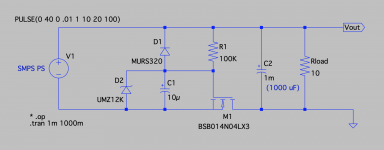
Looking at the circuit I don't see any current limiting component. So I chose to put the circuit into LTSpice choosing some typical numbers. I chose a supply voltage of 32 volts and a load resistance of 10 ohms. The FET chosen was one of the available devices already in LTSpice, a BSB014N04LX3.
The simulation confirmed my expectations. There's no current flowing from the supply for about 10 milliseconds until Vgs across the FET reaches its threshold value. Then it turns on and sinks current from the load and 10000uF cap and in the span of 2 milliseconds charges the cap to full voltage with a peak current approaching 300A. A typical SMPS won't support peak currents like that. And if you make a first order approximation of (32V/2*(300A/2) power in 2 milliseconds for the energy that must be absorbed by the FET it isn't obvious to me that it would survive.
You would be better off with using a current limiting device such as an NTC or resistor to limit the current and short across it after a suitable time delay. I also would not use a 10000uF cap on the load side of an SMPS.
correction to my post. Peak current in the simulation is a bit over 200A. My conclusions and recommendations stand.
Jhofland, try your #488 suggestion in LTSPICE. When the shortie-outie device (relay contacts) shorts out the resistor/ICL, kaboom! Current drawn from the SMPS goes through the roof: hundreds of amperes again. Even if the cap has been charged up to within 500mV of its final value, dV/dt is big when dt is small (as it is when a relay closes). Thus I = C*dV/dt is enormous. The small dV isn't enough to make the problem go away.
One (expensive) way around the problem is to use MOSFETs with not-so-low Rdson as the shortie-outie devices. You may want two of them in parallel, with different Rdson ratings, switched at different times.
If you switch them when Vds < (SMPS_max_rated_current * Rdson), the SMPS won't go into current limiting or Hiccup mode.
inrush limiting
Mark,
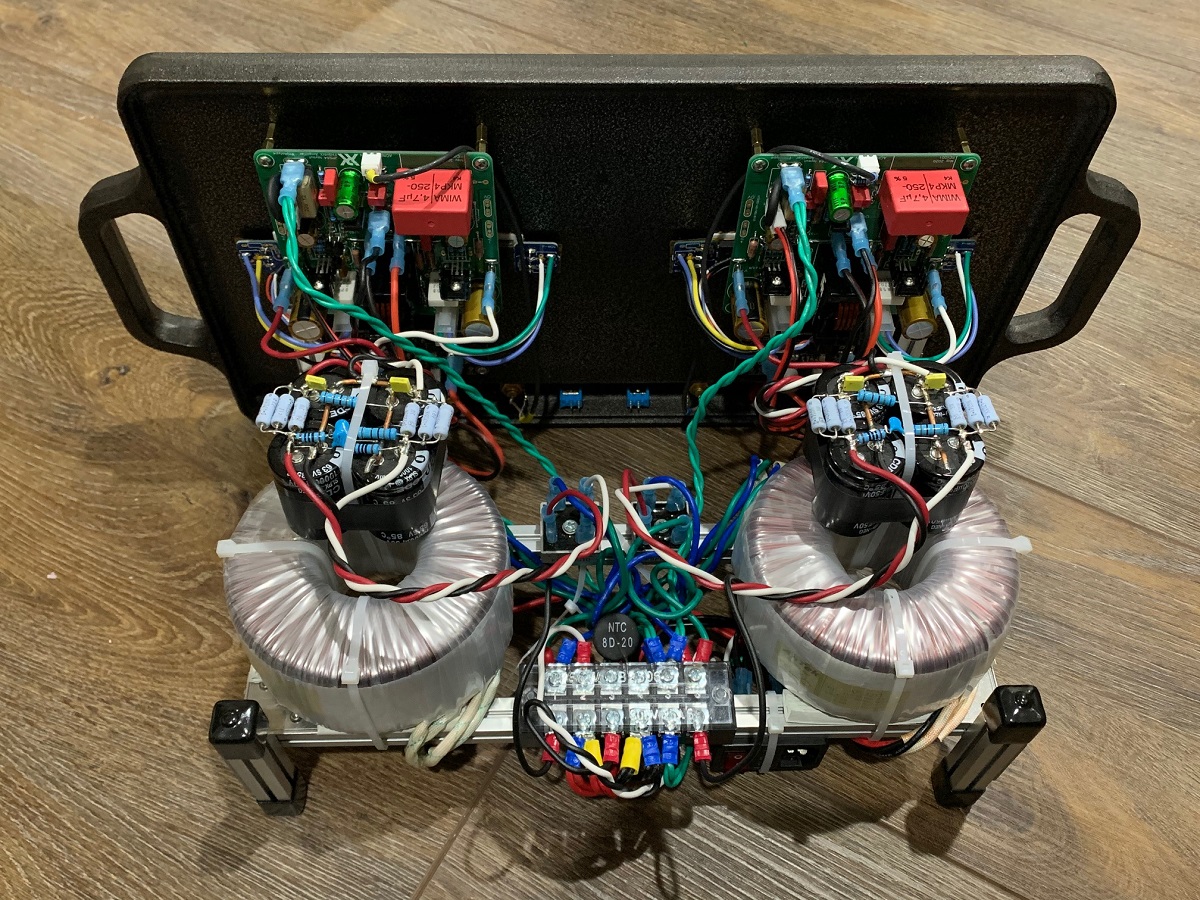
I have, in fact, built and tested an inrush current limit circuit using an NTC and a shorting MOSFET for use between an SMPS supply and an amplifier. The schematic is attached somewhere here.
It works reliably. No KABOOMS
Mark,
I have, in fact, built and tested an inrush current limit circuit using an NTC and a shorting MOSFET for use between an SMPS supply and an amplifier. The schematic is attached somewhere here.
It works reliably. No KABOOMS
Attachments
Hi dBel,
Thanks for the update. I am glad that it gets better with age, like a good red wine.
I also leave mine on - 24/7. I don’t even bother turning it off anymore as it runs pretty cool. The griddle never gets hot enough to cook on that’s for sure. 🙂
Thanks for the update. I am glad that it gets better with age, like a good red wine.
I also leave mine on - 24/7. I don’t even bother turning it off anymore as it runs pretty cool. The griddle never gets hot enough to cook on that’s for sure. 🙂
@wtnh:
Looking at the circuit I don't see any current limiting component. So I chose to put the circuit into LTSpice choosing some typical numbers. I chose a supply voltage of 32 volts and a load resistance of 10 ohms. The FET chosen was one of the available devices already in LTSpice, a BSB014N04LX3.
The simulation confirmed my expectations. There's no current flowing from the supply for about 10 milliseconds until Vgs across the FET reaches its threshold value. Then it turns on and sinks current from the load and 10000uF cap and in the span of 2 milliseconds charges the cap to full voltage with a peak current approaching 300A. A typical SMPS won't support peak currents like that. And if you make a first order approximation of (32V/2*(300A/2) power in 2 milliseconds for the energy that must be absorbed by the FET it isn't obvious to me that it would survive.
You would be better off with using a current limiting device such as an NTC or resistor to limit the current and short across it after a suitable time delay. I also would not use a 10000uF cap on the load side of an SMPS.
OK - I did not simulate the circuit and I can see your point - what if the time constant were increased significantly so that the MOSFET was in its linear region for a sufficient length of time to allow the load cap to not incur a huge inrush (low enough not to kill the MOSFET or cause the SMPS to hiccup)?
I have, in fact, built and tested an inrush current limit circuit using an NTC and a shorting MOSFET for use between an SMPS supply and an amplifier. ... It works reliably. No KABOOMS
Was there a big (greater than, say, 22,000 uF) capacitor downstream? If so I'm surprised.
If the NTC charges the cap up to within 0.5V of the SMPS output, and then the MOSFET does the rest within 200 microseconds, then dV/dt = 0.5/2E-4 = 2.5E3 and I = C * dV/dt = 2.2E-2 * 2.5E3 = 55 amperes. And yet the SMPS doesn't current limit (?!)
Anyway it's good news all around, and thanks very much for sharing your experience and your actual circuit schematic!
_
Attachments
Hello Mark,
There was not a huge capacitance on the load for a couple of reasons. As I'm sure you know, you don't need nearly the capacitance when using a SMPS with microsecond switch periods vs a line operated supply with switch periods on the order of 10 milliseconds.
@wtnh,
rerunning the simulation with 10x time constant does reduce the peak current to around 40A. What helps even more is to reduce the load capacitance by a factor of 10.
-Jan
Ok - that's a good result. Obviously to make this practical, one needs to consider the start-up characteristics of the SMPS as well as the desired downstream load capacitance and the current rating of the MOSFET. 10,000 uF was just a "plug" value to get the discussion started. More realistically, 1,000 uF or less per amplifier rail should be acceptable for de-coupling purposes.
As X mentioned, the FH9HVX uses 470uF per rail.
The MOSFET I mentioned previously is good for 120 Amps continuous.
Also - a Zener is definitely needed to limit Vgs - many MOSFETs have a spec around +/- 20 Volts max, so a 12 Volt Zener would allow a typical device to reach its minimum Rdson while maintaining a good safety margin.
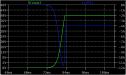
Following @jhofland's lead, I ran an LTspice simulation using the MOSFET he picked, the BSB014N04LX3.
I assumed a 40 Volt SMPS input with a 10ms rise time, a 1000 uf load cap, and a 10 Ohm resistive load.
The output voltage increases smoothly over a period of about 8 ms. The current through the MOSFET increases smoothly over the same period to a peak of about 11.5 Amps and then settles quickly to a steady-state load current of 4 Amps.
So I think this simple circuit has value for the use case we have been discussing and I may make up a circuit board for a SMPS-powered FH9HVX amp.
Feel free to play around with the .asc file and the conditions I picked.
Attachments
Hi Wtnh,
Thanks for doing that. Can we replace replace C2 and Rload with the actual amp's capacitance and load? That is, in practice, leave those components off.
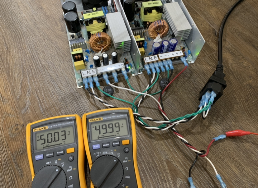
This would be a great workaround to this hiccupping SMPS issue that I sometimes get when running certain PSU's with certain amps. I have a pair of 800w 48v SMPS that I can hook up in series for daul-rail and it would be nice to be able to do this. For two +48v SMPS connected in series with the common connection being 0v ground, would one of these circuits each be needed in between the +ve out of each SMPS?
Can the MUR diode be replaced by standard 1N4148? Still will use the 12v zener to protect the MOSFET.
Post 28 of this thread:
FH9HVX - Budget Conscious 100w Class AB for Lean Times
Thanks for doing that. Can we replace replace C2 and Rload with the actual amp's capacitance and load? That is, in practice, leave those components off.
This would be a great workaround to this hiccupping SMPS issue that I sometimes get when running certain PSU's with certain amps. I have a pair of 800w 48v SMPS that I can hook up in series for daul-rail and it would be nice to be able to do this. For two +48v SMPS connected in series with the common connection being 0v ground, would one of these circuits each be needed in between the +ve out of each SMPS?
Can the MUR diode be replaced by standard 1N4148? Still will use the 12v zener to protect the MOSFET.
Post 28 of this thread:
FH9HVX - Budget Conscious 100w Class AB for Lean Times
Last edited:
If the "Protective Earth" (3rd wire in the IEC mains connector) is separated from chassis ground, that makes me nervous.
Hi Wtnh,
Thanks for doing that. Can we replace replace C2 and Rload with the actual amp's capacitance and load? That is, in practice, leave those components off.
This would be a great workaround to this hiccupping SMPS issue that I sometimes get when running certain PSU's with certain amps. I have a pair of 800w 48v SMPS that I can hook up in series for daul-rail and it would be nice to be able to do this. For two +48v SMPS connected in series with the common connection being 0v ground, would one of these circuits each be needed in between the +ve out of each SMPS?
Can the MUR diode be replaced by standard 1N4148? Still will use the 12v zener to protect the MOSFET.
Post 28 of this thread:
FH9HVX - Budget Conscious 100w Class AB for Lean Times
Yes - the output capacitor and the load resistor are only there for simulation; they would be omitted in an actual application.
You would need 2 of these, one for each supply if I understand your hookup correctly. I am assuming the supply outputs are floating (which allows you to ground either the + or - lead to the amp ground in your current configuration). Since the MOSFET limiter is essentially floating also (and can be considered a 4 terminal "black box"), it really does not care where the ground reference is. In other words, you could ground the positive output lead (marked Vout) and use the node marked with the ground symbol for the negative supply rail.
So you would create the series and ground connections AFTER the limiters, letting the SMPS outputs float. If that's not clear, I'll try an actual schematic.
Chassis grounds would need to be connected to the IEC safety ground for sure. Also, the usual chassis safety ground to amp power ground lifter would be appropriate.
You will need a beefier N-channel MOSFET than the one I show for your 48 Volt supplies. I believe the one I simulated is only rated to 40 Volts. Let me know what you have laying around and I'll see if there is a model available for it. The main parameters of concern after max Vds are high current capability and very low Rdson.
I don't think the diode is critical - LTspice shows very little current flow through it so a 1N4148 should be fine. It just needs have a peak reverse voltage greater than the supply. Also, the Zener could be any old 12 Volt device. It just clamps the gate to a safe value.
Last edited:
- Home
- Group Buys
- FH9HVX - Budget Conscious 100w Class AB for Lean Times