Hello,
Recently ordered SA9227 based USB ↔ I2S converter and decided to check distortions of the converter itself making I2S loopback.
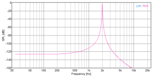
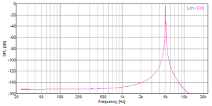
The results look strange to me. I expected a symmetrical spectrum, but there is always a horizontal “shelf” on frequencies below the test signal.
I would admit the shelf on the both sides or downward curve on the both sides (of the test signal) as well, anyway a symmetrical curve.
The “shelf” goes down with the test signal frequency increasing and goes up with decreasing.
The “shelf” goes down with FFT size (quantity of points) increasing and goes up with decreasing.
What could be a reason/explanation of such behavior? The converter specifics? The measurement specifics? Something else I’ve missed?
Thanks in advance,
Serge
Recently ordered SA9227 based USB ↔ I2S converter and decided to check distortions of the converter itself making I2S loopback.
The results look strange to me. I expected a symmetrical spectrum, but there is always a horizontal “shelf” on frequencies below the test signal.
I would admit the shelf on the both sides or downward curve on the both sides (of the test signal) as well, anyway a symmetrical curve.
The “shelf” goes down with the test signal frequency increasing and goes up with decreasing.
The “shelf” goes down with FFT size (quantity of points) increasing and goes up with decreasing.
What could be a reason/explanation of such behavior? The converter specifics? The measurement specifics? Something else I’ve missed?
Thanks in advance,
Serge
Attachments
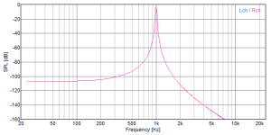
Hanning, other methods produce obvious artifacts. Size - tried various, that one was taken on 2048. Using 16384 shows the same shelf just at a lower level, the shelf level is signal frequency dependent anyway
That curve is definitely spectral leakage, perhaps you haven't accounted for the latency in DACs/ADCs and prematurely started sampling. You want to send continuous sample stream and only start reading samples say a few ms after it starts - my guess is you are seeing leading zeroes in the loopback which would produce spectral leakage like this.
Audio sigma-delta converters have dozens of samples latency each way, they are not like flash or SAR converters commonly used for other signal acquisition uses.
Audio sigma-delta converters have dozens of samples latency each way, they are not like flash or SAR converters commonly used for other signal acquisition uses.

Can you describe the loopback in more detail. Does your board support both I2S output and input?It's pure digital (I2S) loopback.
Ah, is the signal generated isochronous to the FFT sampling? If not you might just be seeing the Hann window spectral leakage. Can you use a higher performance window function? Or up the size of the FFT considerably, like 256k points?There are no AD/DA conversions at all. It's pure digital (I2S) loopback. Also the FFT is alive, taken periodically/continuously, not momentarily, So it's still a puzzle
I find high performance window functions (very low side lobes) essential when analyzing high-precision audio signals asynchronously, I recommend reading this: https://holometer.fnal.gov/GH_FFT.pdf - it covers very clearly some of the issues glossed over all too often in material about frequency analysis using the discrete Fourier transform (i.e. FFTs).
The "big hammer" approach works well too. I run 4-32M point FFTs with a Hann window. A modern computer is a very big hammer. 😉
Ed
Ed
I have noticed a similar effect on simulations of circuits that have high-pass, lack of low frequency response.

I've done such test with my USB<->I2S project:

The only time there was an issue - it was related to improper slave/master configuration. I am not familiar with SA9227 but are you sure that I2S output is configured as master (generates BCK, WCK) and the input port is slave (expects external BCK, WCK)?
If input port is configured as master - you'll need ASRC for such loopback test (well, it is one of the options).
PreciselyCan you describe the loopback in more detail. Does your board support both I2S output and input?
Are the I2S input/output streams synchronous (use same clock)? If not the problem is quite likely with spectral leakage as some already suggested. Try with another FFT window and e.g. 64k FFT size.
Those have the appearance of unwindowed data. Check whether the Hann window is being applied, or being applied correctly.What could be a reason/explanation of such behavior?
DATA out - > DATA in. LRCLK out -> LRCLK in. BCLK out -> BCLK in. MCLK out -> MCLK in (the latter may be connected and may be not, the result is the same)Please share exact connections
Alright, let's do a simple test with multimeter.
Measure voltage on BCK, WCK out. There should be ~1.6v during operation.
Disconnect BCK and WCK inputs and measure voltage here. If they are inputs - there should be 0 or 3.3v.
(BTW, is there any documentation for this module?)
Measure voltage on BCK, WCK out. There should be ~1.6v during operation.
Disconnect BCK and WCK inputs and measure voltage here. If they are inputs - there should be 0 or 3.3v.
(BTW, is there any documentation for this module?)
It's the single USB board with 3 TXCOs. In and Out are on 48k everywhere (board/FFT/generator), so probably the clock source on the board is the same. The PC based clock (48k) is different, but WSAPI is used in the software. So hope the streams are synchronous. Anyway I don't know a way to check the clock inside the PC. Scheduled some experiments and will post the results. The most promising idea for me know is "signal generated isochronous" related. And the purpose is still to understand the shelf appearance reason, not to make the shelf lowerAre the I2S input/output streams synchronous (use same clock)? If not the problem is quite likely with spectral leakage as some already suggested. Try with another FFT window and e.g. 64k FFT size.
Oscilloscope is better isn't it. All levels/shapes fit the expectations, TTL etc etc, Disconnecting any of the pins breaks the signal as expected. The problem doesn't look HW related at all. I guess it's somewhere around clocking/synchronicityAlright, let's do a simple test with multimeter.
Measure voltage on BCK, WCK out. There should be ~1.6v during operation.
Disconnect BCK and WCK inputs and measure voltage here. If they are inputs - there should be 0 or 3.3v.
(BTW, is there any documentation for this module?)
Unfortunately just SA9227 datasheet publicly available only. FW is not disclosed at all(BTW, is there any documentation for this module?)
- Home
- Design & Build
- Equipment & Tools
- FFT of digital loopback