Idefixes
I think Your 3 pair board is better designed from thermal point of view, the temperature sensor is located between ops transistors. In my case the temperature of bias sensor is approx 5-6 celsius lower than ops transistors.
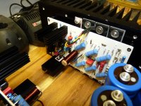
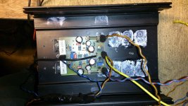
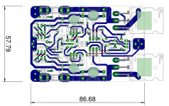
Ok. I have the ability to mount direct on a output device as i made on BG1-MJL or my Nbip (see attached picture)
Attachments
Recommendations for audio amplifier
Hi guys!
I see you have developed a multivariate amplifier.
Which amp would suit me the output MOSFETs and the BJTs tansistors, as we have in the power supply Ucc = +/-(35 ....40)V, Po = 220VA and spekers with impendans 4R.
So give recommended some any of your Amplifier that provides a defined exactly bass!😉
This applies to you, Mr Borys and Mr Indefixes.
Thanks the recommendation.
Cheers!
Last edited:
Hi gaborbela!Marc those PC boards design and quality just awesome!🙂 especially known is all hand crafted😀😀
Congrat..
Today I made the layout for the LatFet version, I have some high power dual diy EXICON and Class D mosfets, I would like to test those to.
I do have a 39-0-39V 600VA transformer for that project.
If your Capmu. work with these topology well I will use that to get some voltage drop for the one pair LatFet.
To replace the BC550/560 high Hfe BJT I still need to look around on the market and also the JFet has to be replaced by BJT.
So the lay out still need some adjustment, not 100% ready.
I separated the SGR from the main GR.
I took some of your idea for the layout, it helped alot - thank you!
Soon I'll start to make the PC boards so I can test all 4 VERSION 😱
Power BJT
Toshiba
LatFet
Darlington
Greetings Gabor
Please give show Top brd in pdf (PCB-top) of the amplifier.
Thank you!
Attachments
Last edited:
Hello
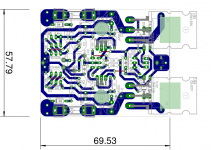
These layout for LatFet version only!
The tread about HexFet, or Power BJT.
What type do you want to build, please let me know- may be I or someone from these forum can help you.
We must know what do you want to build, already existing material etc.
Greetings Gabor
These layout for LatFet version only!
The tread about HexFet, or Power BJT.
What type do you want to build, please let me know- may be I or someone from these forum can help you.
We must know what do you want to build, already existing material etc.
Greetings Gabor
Audio amplifier BJT with 2sc5299/2sa1943
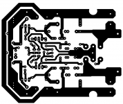
PCB-layot and PCB-botton,
cheers!
Power BJT!Hello
These layout for LatFet version only!
The tread about HexFet, or Power BJT.
What type do you want to build, please let me know- may be I or someone from these forum can help you.
We must know what do you want to build, already existing material etc.
Greetings Gabor
PCB-layot and PCB-botton,
cheers!
Ghost22
Bellow version that I am running with 4 or less output pairs.
For 200W I suggest to use 2 pairs of outputs.
BJT:
Do not solder 4 diodes (D1,D4,D5,D6)
Mosfet:
Solder diodes, and replace 2,2r base stoppers with 100R gate resistors.
Some tweak in biasing circuit may be required.
In the picture of my amp there are 2n5xx1 transistos soldered - they are reversed to BCxxx ones. If you need smaller pcb - cutt earth around the board and do not solder the caps next to the o/p transistors. PCB is for 4 pairs, trim the board before for 1,2,3 or 4 pairs before thermotransfer. Amp is very easy to assemble.
For one pair of toshiba mosfets I have build small pcb (removed one driver stage).
Attachments


Ghost22
Bellow version that I am running with 4 or less output pairs.
For 200W I suggest to use 2 pairs of outputs.
BJT:
Do not solder 4 diodes (D1,D4,D5,D6)
Mosfet:
Solder diodes, and replace 2,2r base stoppers with 100R gate resistors.
Some tweak in biasing circuit may be required.
In the picture of my amp there are 2n5xx1 transistos soldered - they are reversed to BCxxx ones. If you need smaller pcb - cutt earth around the board and do not solder the caps next to the o/p transistors. PCB is for 4 pairs, trim the board before for 1,2,3 or 4 pairs before thermotransfer. Amp is very easy to assemble.
For one pair of toshiba mosfets I have build small pcb (removed one driver stage).
Hi Borys
Can I use your pcb with one pair 2sc5200/2sa1943.
If could, so can you post this layout in PDF file and Eagle file
Thanks.
For one pair of outputs there is another version of pcb.
You can use this above with one pair too. I will post evening time eagle file for you.
You can use this above with one pair too. I will post evening time eagle file for you.
For one pair of outputs there is another version of pcb.
You can use this above with one pair too. I will post evening time eagle file for you.
Hi Borys!
Copper in the holes where the components are soldered to the PCB to amplify drill 1mm, since I can not find a drill of 0.7 or 0.8 mm?!🙄😕(
thank you!
fet
Wich is your Eagle version?
Thanks.
Hi borys .I can't see these files .The eagle files.
Wich is your Eagle version?
Thanks.
fet hexfet
Where is 1 pair BJT version?
Where is 1 pair Fet version?
Best regards.
Thimios.
Ok. thanks.6.2.0
Is my version.
Where is 1 pair BJT version?
Where is 1 pair Fet version?
Best regards.
Thimios.
O sorry, I will upload 1 pair version too. No worries.
Hope do not forget heh
I have very good memory but bit short.
Hope do not forget heh
I have very good memory but bit short.
fet hexfet
Ok don't worry i can remind you.🙂
O sorry, I will upload 1 pair version too. No worries.
Hope do not forget heh
I have very good memory but bit short.
Ok don't worry i can remind you.🙂
Bellow bg1-bjt and BG1 mosfet (without the drivers).
BJT version with drivers can be used with mosfets too, just replace base resistors with 100R and putt zeners from output to gates of mostets (I didnt have time to putt them).
BJT version with drivers can be used with mosfets too, just replace base resistors with 100R and putt zeners from output to gates of mostets (I didnt have time to putt them).
Attachments

fet hexfet
Try again.🙂
Thanks borys but....you have uploaded the same zip.Bellow bg1-bjt and BG1 mosfet (without the drivers).
BJT version with drivers can be used with mosfets too, just replace base resistors with 100R and putt zeners from output to gates of mostets (I didnt have time to putt them).
Try again.🙂
fet hexfet
What about the sound of this?
Regards.
Thimios.
Ok borys fine.Sorry
What about the sound of this?
Regards.
Thimios.
The core of the amp is vssa based and this one has good opinion.
What diffrence I found is bottom end is better presented (prapobly due to BJT at output).
The other diffrence I found is the amp without signal is dead quiet.
I think Idefixes was listening this amp bit more than me. I have to finish my speakers first to do proper A and B test. Overal it it very simple and good sounding amp with good kick on bottom end (bjt)
- Home
- Amplifiers
- Solid State
- FET-hex explendit amplifier