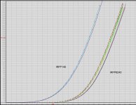
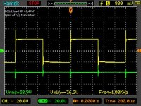
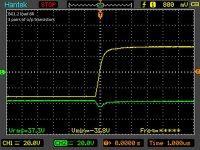
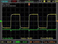
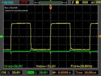
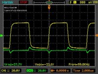
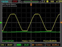
If you have a chance please check high speeds transients of the above transistor pairs. THD on pair irfp240/9140 is very good and amp behaves really good on square tests. I will test later on irfp240/9240 pair as suggested. (I remember I had some unsymetric scope measurements with those).
The current output of irfp240/9140 is a closer match, that`s probably why they behave better on capacitive loads.
But as far as transconductence this is a much better pair,even though they have a different Vgs off point...
To better this you will have to get the Japanese or British audio Mosfets.
Attachments
Amplifier with transistors pair MJ15003/MJ15004
Hi Borys!
I have available two transistors pairs MJ15003/MJ15004 for stereo audio amplifier😉, power supply Ucc=+/-40V with Po=250VA and speakers with impedance of 4R.
Please, can you recommend the schematic for audio amplifier and PCB for this variant.
Thank you for your cooperation and help!
Hi Borys!
I have available two transistors pairs MJ15003/MJ15004 for stereo audio amplifier😉, power supply Ucc=+/-40V with Po=250VA and speakers with impedance of 4R.
Please, can you recommend the schematic for audio amplifier and PCB for this variant.
Thank you for your cooperation and help!
Last edited:
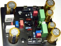
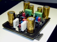
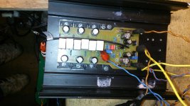
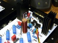
VERSATIL evo "Black Edition". Evo means use of smd parts to reduce board size. I don't find time yet to fix it on heatsink😡😡😡
Marc
Marc
Attachments

HI peter,
if you don't have 2SC5200/2SA1943 consider NJW3281/1302, package is smaller and SOA better, also Onsemi clair in Datasheet that "NPN/PNP Gain Matching within 10% from 50 mA to 5 A". In SOA terms they are quite near MJL4281/1302 but un TO3P package...
I will use them in VERSATIL 100 version. Board size : 110x80mm. +/-50Vdc rails
Marc
Attachments
Last edited:
HI peter,
if you don't have 2SC5200/2SA1943 consider NJW3281/1302, package is smaller and SOA better, also Onsemi clair in Datasheet that "NPN/PNP Gain Matching within 10% from 50 mA to 5 A". In SOA terms they are quite near MJL4281/1302 but un TO3P package...
I will use them in VERSATIL 100 version. Board size : 110x80mm
Marc
I have a couple pairs ofmjl4281/4302 left so I can try them anyway. I will check NJW tranies too.
But one thing about 2sc5200/1943 pair I know that they can surviwe bit more than is in datasheet, the are very good tranies and availible anywhere. Try to drive them till they give up!
BTW what does the versatil mean in english ??
thx
Last edited:
Idefixes
Do not think that I am doing nothing at all. Bellow high voltage version in progress. Nice work.
What rail voltage will be you be using? Will there be a corresponding Voltage supply board for this?
Thanks
BTW what does the versatil mean in english ??
thx
That's more in french and mean can be easy change to...was to the ability to use wether BJT nore VMOS just by adding 2 zener..
Marc
Hi Marc,
What ever happend with using BC546C/BC556C for the front end??
Did they match in the gain??
Thank you...
What ever happend with using BC546C/BC556C for the front end??
Did they match in the gain??
Thank you...
Hi Marc,
What ever happend with using BC546C/BC556C for the front end??
Did they match in the gain??
Thank you...
Not use at time 556/546 due Vrail i use => +/-35vdc in versatil 50 so BC550C/560C fit perfectly the job.
Marc
Hi Marc,
What ever happend with using BC546C/BC556C for the front end??
Did they match in the gain??
Thank you...
Hi BenY, I used the BC546B/BC556B at the input of a similar amp ( or the same ?) . Works very well and safe up to much higher rail voltages. While it has less gain and is noisier then the BC550C/BC560C , the resulting amp is noise free. No hiss no hum near the speakers.
I believe that BC546C and BC556C are also available. But the C will only help to get the dc offset down. In any case it is so low already it doesn't seem to matter. My B devices measured 317 / 325 for the npn/pnp .
An equivalent for the BC550C/BC560C could be the 2SC1815/2SA1015 GR grade. They are also rated for 50 V.
Zero bias
Acca, I tried the zero bias output stage.
Check the result at
http://www.diyaudio.com/forums/soli...diy-amplifier-20-years-go-50.html#post3669674
Acca, I tried the zero bias output stage.
Check the result at
http://www.diyaudio.com/forums/soli...diy-amplifier-20-years-go-50.html#post3669674
Hi,
That's the BJT version? could you give more details to what you use as the rail voltage....
In the future buiding i let the possibilty to install a inductor at output, i curious about your version (without inductor) stablility...
Marc
That's the BJT version? could you give more details to what you use as the rail voltage....
In the future buiding i let the possibilty to install a inductor at output, i curious about your version (without inductor) stablility...
Marc
Last edited:
Hi,
That's the BJT version? could you give more details to what you use as the rail voltage....
In the future buiding i let the possibilty to install a inductor at output, i curious about your version (without inductor) stablility...
Marc
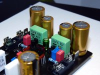
I am going to push it up to +/-80V (but at the moment I do not have proper caps, i have only 63V ones). This is wathever you solder version - at the moment BJT. Input 2n5xx1, I think that +/-100V should be fine, small tune up may be required for higher voltage. I do not plan any bootstrap for this version. Inductor and zobel are fitted on PSU board (check few pages before, there is somwhere my PSU unit). I hope tomorrow I will test stability and rest of the parameters.
Just quick if all looks ok. Seems that putting more transistors at o/p stage only improves the amp.
Attachments

Hi,
I check few pages before and found your 25 and 35 PSU files. Ok Zoebel are there but What about inductor, seems not to be on board. Not an issue just to see what specifications you apply to this inductor. Good to see that adding output devices seems nor degrad but improve amp behavior.
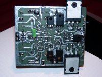
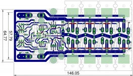
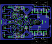
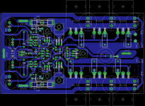
The latest layout i have under way integrate inductor and zoeble on board. (picture under). Inductor will be vertical (as my Nbip) so no issue to change its value...
I check few pages before and found your 25 and 35 PSU files. Ok Zoebel are there but What about inductor, seems not to be on board. Not an issue just to see what specifications you apply to this inductor. Good to see that adding output devices seems nor degrad but improve amp behavior.
The latest layout i have under way integrate inductor and zoeble on board. (picture under). Inductor will be vertical (as my Nbip) so no issue to change its value...
Attachments
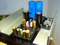
The inductors are winded up on the resistors.
Today I have tested the temperature compensation, amp is undercompensated so I will have to improve compensation slightly.
Thanks it's more clear....don't hesitate to report your work on "compasation".
Marc
Idefixes
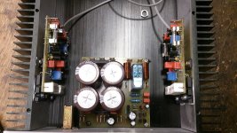
I think Your 3 pair board is better designed from thermal point of view, the temperature sensor is located between ops transistors. In my case the temperature of bias sensor is approx 5-6 celsius lower than ops transistors.
I think Your 3 pair board is better designed from thermal point of view, the temperature sensor is located between ops transistors. In my case the temperature of bias sensor is approx 5-6 celsius lower than ops transistors.
- Home
- Amplifiers
- Solid State
- FET-hex explendit amplifier