The wire diameter ( or cross sectional area) should be decided on the Irms of that winding. Right?  ie the the one we discussed (500A/sqcm). so we say 0.2 Sqmm/Amp. may be if we need 4 amp it would be 4*0.2 = 0.8Sqmm. that would roughly be 18AWG. But lets say we are using 100Khz which limits us to use 26AWG. so 0.8/0.129 = 6.2 , rounding it to 6 strands of 26AWG.
ie the the one we discussed (500A/sqcm). so we say 0.2 Sqmm/Amp. may be if we need 4 amp it would be 4*0.2 = 0.8Sqmm. that would roughly be 18AWG. But lets say we are using 100Khz which limits us to use 26AWG. so 0.8/0.129 = 6.2 , rounding it to 6 strands of 26AWG.Yes on the Irms question.
I am not a big fan of using Current density for the calculations. I prefer to use power dissipation instead.
I believe that we are talking about a 90V output and 1A. The most I would use is 2xAWG26 on the secondary and 1x for the primary. If you were doing 5V on the output and delivering 18A then we would be having a different discussion.
Let's talk again about current density...
First... you can use infinitely thin wire if the current is low enough, alternatively if wire length is short enough you can run huge currents through it. I guess what I am saying is what we are really talking about is wire temperature.
Since current is a ^2 term, any time you can get I<1A then you have a really small term. However, when I is >>1A you have a real problem. At 200A I^2 would mean any resistance I have would be multiplied by 40000. That is a truly huge number even if you are using 0.001 ohms (that would be 40W). This is why the server guy's use multiple sync FET's to drive the Rdson of <<0.001. They also use multiple phases to drive the sycn FETs so they can spread the heat around.
So, am I in agreement with McLyman in his use of current density? Not really. However, I can say if you use is approach you will not have a problem with heat dissipation. However, you may well have an issue with the wire fitting on the bobbin.
So, what do I suggest? Take a look at your design calculations and use the black body model which we have already described and see what you think the DeltaT is on a single strand of 26AWG copper wire. if you come out with anything <20C DeltaT rise then you should be good. I haven't ran those numbers on this design so let me know what you find.
If you are wondering why I said 20C... The safety limit for standard enamel wire is 110C. Assuming you are at about 90C for the core material that leaves 20C for your design margin.
I will say that wire gauge selection is often an iterative process that I will do a couple times during the design phase. I will look at overall efficiency and my temperature over the gap in the transformer to determine if the assumptions I have made are acceptable.
Let me know what you think.
Tony
Tony
I agree, The thumb rule method is the most easiest way but the most inappropriate way of finding the wire gauge.
"I believe that we are talking about a 90V output and 1A. The most I would use is 2xAWG26 on the secondary and 1x for the primary. If you were doing 5V on the output and delivering 18A then we would be having a different discussion."
Yes , I am going to make a prototype from whats designed during lessons. But before I jump to construction of transformer. I want to understand equations for flyback transformer very well. With the same purpose I picked an example from McLyman, put it in excel sheet. and by varying input parameters I was studying how different output parameters change.
But I got some doubts. I would request you to comment on thread #120.
If you are wondering why I said 20C... The safety limit for standard enamel wire is 110C. Assuming you are at about 90C for the core material that leaves 20C for your design margin.
I will say that wire gauge selection is often an iterative process that I will do a couple times during the design phase. I will look at overall efficiency and my temperature over the gap in the transformer to determine if the assumptions I have made are acceptable.
Let me know what you think.
Tony
Tony
🙂 I would say This is like designing an enclosure for a given driver. calculations can always take you close to result you want to achieve. But to get it perfect you always need to trim.
but later when you master the art (like you 🙂 ) you know exactly where to strike to get results you want.
Sorry for missing your points on 120...
1) By this do you mean the power dissipation of the transformer or are you talking about the power handling capacity?
2) My apologies if I get your question wrong... If you change he power the secondary needs then you will have to adjust the duty cycle for the primay. When yo adjust that parameter, the other secondary will alsi change because the duty cycle had to change. The correct design procedure is to take the total power for the secondaries and use that (divided by your expected efficiency) t0 design the primary (duty cycle and flux ensity) and then you design the secondaries. This way everything is automatically adjusted when you make a change to your power at the top of the spread sheet.
You may want to change the way you calculate Ipk so that you can use the same calculations for DCM as you do for CCM operation. See my notes on the CALC-1 sheet.
Id=Pin/(Vinmin*DutyCycle)
DeltaI=200%*Idc (For CCM you would have a smaller number for the Percent something like 25%
Ipk=Idc+(DeltaI/2)
For Lp you have to use Ipk so Vinmin*Ton/Ipk so you end up needing 70uH. I will have a few more notes afterwhile.
Tony
Id=Pin/(Vinmin*DutyCycle)
DeltaI=200%*Idc (For CCM you would have a smaller number for the Percent something like 25%
Ipk=Idc+(DeltaI/2)
For Lp you have to use Ipk so Vinmin*Ton/Ipk so you end up needing 70uH. I will have a few more notes afterwhile.
Tony
I am going to shortcut the rest of his stuff... What is really important is you peak Flux density. First we assign the operating flux density we want to operate at and then we back into everything els.
Np=(Lp*Ipk)/(Bm*Ae) that gives you 21 turns for 3700 gauss. That is what you to figure out how to get into the bobbin.
Tony
Np=(Lp*Ipk)/(Bm*Ae) that gives you 21 turns for 3700 gauss. That is what you to figure out how to get into the bobbin.
Tony
If you are uncomfortable at 3700 gauss you can drop to 2800 and you will need 28 turns I believe.
I will let you go work out the fringing flux.
FYI... I no longer you the current density and Area Product for the transformers.
Tony
I will let you go work out the fringing flux.
FYI... I no longer you the current density and Area Product for the transformers.
Tony
Sorry for missing your points on 120...
1) By this do you mean the power dissipation of the transformer or are you talking about the power handling capacity?
2) My apologies if I get your question wrong... If you change he power the secondary needs then you will have to adjust the duty cycle for the primay. When yo adjust that parameter, the other secondary will alsi change because the duty cycle had to change. The correct design procedure is to take the total power for the secondaries and use that (divided by your expected efficiency) t0 design the primary (duty cycle and flux ensity) and then you design the secondaries. This way everything is automatically adjusted when you make a change to your power at the top of the spread sheet.
Reference Example: " I am using same example as in book.( Chapter 13. Design Example, Buck-Boost Isolated Converter Discontinuous Current)"
@ 1 ) I meant if my example is designed for 18.5W (from McLyman). so is the core selected(selected by author during example). so what I do is I drop down total wattage by varing secondary current, to 6W. Then In this case I am not changing Dutycycle and min voltage at primary. So here the turns should remain unchanged but the thickness if the wire should change to thinner wire also reducing number of strands in litz wire.
Is my above assumption correct ? (hope the word assumption is correct in this case )
If my assumption is correct, then the calculations (equations) provided in the example does not support my assumption. I would request you to check it.
to ease the calculations I have made the excel file which is zipped and attached in my previous reply #125.
You can replace values and check.
new values:
Input voltage nominal, Vin = 28 V
Input voltage Minimum,Vin min = 24 V
Input voltage Maximum,Vin max = 32 V
Output Voltage V1 = 5V
Output Current I1 = 0.4 A
Output Voltage V2 = 6 V
Output Current I2 = 0.5 A
The Area of the wire is Awb=PI()(r)^2
The Lp resistance is RcuPri=(Rho.e/Awb)*MLT*Np (told you we would eventually use it).
We will approximate the RMS current (there are precise calculations to do that and I will let you find them) by using the PawbPri=(Po/(n(90Vac*sqrt(2))))^2*(RcuPri) where n is the efficiency. If this number is acceptable (about 115mW for the primary winding).
Next is the secondary side...
Tony, did you mean to say
PawbPri = (Primary RMS current )^2 * RcuPri .
Given equation above is
PawbPri=(Po/(n(90Vac*sqrt(2))))^2*(RcuPri)
where 90Vac*SQRT(2) will give peak DC. Lets call this as Vinput.
so,PawbPri = (Po/(n* Vinput))^2 *(RcuPri)
Further, Iavarage ie. Iavg = (Po/n *Vinput)
So replacing the equation with Iavg.
PawbPri = Iavg^2 *RcuPri
the link from national semiconductors.
On page no 5 of 21.
Iavg = Po/(Vin*n)
referring to our case Pin = Po/n
and in the national semiconductor pdf. Irms = Iavg/ SQRT(Dutycycle).
So if I go with the equation you gave it is Iavg^2 * R.
and you asked to approximate RMS for this calculation.
Pl. clear my confusion.

Thanks,
1) About fringing flux.
After we calculate air gap & implement it on the core. Should the primary inductance be what we have found by calculation?
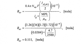
2) Can I use the equation given in McLyman for the calculation of Bac? the equation is.
in the attached picture file.
3) Kcoupling ,
you said
So Lk is a percentage value of LP? and we have to determine Lk by imagining % leakage.
1) About fringing flux.
After we calculate air gap & implement it on the core. Should the primary inductance be what we have found by calculation?
2) Can I use the equation given in McLyman for the calculation of Bac? the equation is.
in the attached picture file.
3) Kcoupling ,
you said
Kcoupling=Sqrt(1-Lk/Lp) If we used 10% leakage then we would have had a 5% error term that would have had to have been factored in.
So Lk is a percentage value of LP? and we have to determine Lk by imagining % leakage.
Attachments
Last edited:
Hopefully I will answer these in order...
1) Yes... But since the fringing flux and air gap affect each other you will iterate the air gap until you reach the calculated Lp.
2) Yes that is correct.
3) Leakage is a physical quantity that occurs as the result of building the transformer. In a transformer it is measured as follows: Attach the LCR meter to the primary winding, short all the other windings together. This inductance that is left is the inductance that is left in the physical structure (winding to winding and to core). A well designed flyback transformer typically exhibits a leakage of about 1% of Lp. Another way of thinking about Lk and Lp is the Kcoupling factor. This is the nonrecoverable portion of the core energy that does not transfer to the output and is considered by most to be the highest fundamental efficiency that is achievable by a core. I am not quite sure if I am expressing this well or not. And I am also certain that others can express it better or have a better understanding of the issue but that is pretty much my interpretation. In general you want to keep Kcoupling high.
Tony
Thanks Tony,
Ok, I got it now. 🙂
About Kcoupling
Thanks for explaining. I am attaching a pdf here pl. check if that is how we calculate Kcoupling. So I would add thin in my calculations.
So the factors affecting Kcoupling are method of winding, neatness in workmanship, and core material?
1) Yes... But since the fringing flux and air gap affect each other you will iterate the air gap until you reach the calculated Lp.
Ok, I got it now. 🙂
About Kcoupling
Thanks for explaining. I am attaching a pdf here pl. check if that is how we calculate Kcoupling. So I would add thin in my calculations.
So the factors affecting Kcoupling are method of winding, neatness in workmanship, and core material?
Attachments
Last edited:
3) Leakage is a physical quantity that occurs as the result of building the transformer. In a transformer it is measured as follows: Attach the LCR meter to the primary winding, short all the other windings together. This inductance that is left is the inductance that is left in the physical structure (winding to winding and to core). A well designed flyback transformer typically exhibits a leakage of about 1% of Lp. Another way of thinking about Lk and Lp is the Kcoupling factor. This is the nonrecoverable portion of the core energy that does not transfer to the output and is considered by most to be the highest fundamental efficiency that is achievable by a core. I am not quite sure if I am expressing this well or not. And I am also certain that others can express it better or have a better understanding of the issue but that is pretty much my interpretation. In general you want to keep Kcoupling high.
Tony
No... there is no problem with your explanation. its perfectly good . Rather I find best. you add your industrial experience to your explanation and I just love it. The other good thin about your explaination is you explain the thing more in logical manner, than just giving equations.
I am lucky to have you here.
Kcoupling=SWRT(1-Lk/Lp) or approximately 100-%leakage so if leakage is 1% of Lp then Kcoupling is about 99% or 0.99. This is also the number you would use if you were running simulations.
You are correct in that the coupling factor is a a function of the core geometry, and spacing inside. Core material does play a roll in that as the permeability changes so doe Lp. I will say that the core shape and wiinding distances play the largest rolls. For example: A long winding window (EER28L) that allows me to put all the windings for the Primary on one layer followed by a tripple insulated secondary using multiple stands and totally covers all the primary windings will have a Higher Q and lower leakage that a core like the RM10 where we have to split windings out. However, the RM10 will have better shielding than a EER28L.
Everything on a transformer is a trade off. What is important is to know which knobs to twist.
Tony
Hello Tony,
From your experience, can you tell me what is the worst case loss or value of Kcoupling. If say randomly wound, or side by side winding is done ( I read side by side winding is least efficient.). This will help me to determine how badly can Kcoupling affect.
From your experience, can you tell me what is the worst case loss or value of Kcoupling. If say randomly wound, or side by side winding is done ( I read side by side winding is least efficient.). This will help me to determine how badly can Kcoupling affect.
- Status
- Not open for further replies.
- Home
- Amplifiers
- Power Supplies
- Ferrite core transformer design step by step