@jxdking,If you can find the optimal value of the resistor by given the inductor, the distortion from the final stage can be canceled out. The overall performance is dominated by the class A stage.
How did you find the corresponding resistance values for your triangle?
You still owe the reader this answer 😉.
OkWhat about into a more realistic speaker load, instead of an 8R resistor?
Such as shown here: https://www.stereophile.com/reference/60/index.html
Here now, but really the last simulation with old spice
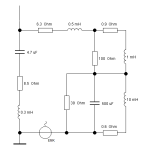
Attachments
I still prefer LTspice VII 64 bits too, simpler to use and more intuitive.For further simulations, I have stored this schematic as a model.
I had mistakenly transformed your triangle 22 - 36 - 36 with 39 ohms instead of 36 ohms, but this will certainly not be so decisive. Rather, the pair 2N3055 & 2N2955 will now also cause a little noticeable transfer x-over distortion in the spectrum.
View attachment 1390676
I am curious.
There is the MC12 64-Bit wonder ...
😉
I mentioned in the OP.How did you find the corresponding resistance values for your triangle?
You still owe the reader this answer 😉.
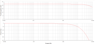
When the corner frequency of the "Forwarding Resistor" and the "Inductor" equals to the "Unit Loop-Gain Bandwidth" (or the close loop -3dB bandwidth, they are same), the circuit is balanced.
Here is "Loop-Gain" bode plot of the circuit in #6. "Loop-Gain" means it includes the voltage divider from the feedback network.
You see it cross over 0dB at 600KHz.
You know the inductor is 4.7 Ohm. It is not hard to calculate that the resistor should be 18 Ohm. In the post #6, there are 2 resistor in parallel. Thus, they are 36 Ohm each.
You can also hand calculate the "Unit Loop-Gain Bandwidth" without simulation, if you can.
If the complex load is still made of ideal resistors, caps, and inductors, it is still a linear load. As long as the load is linear, it should not affect THD much.What about into a more realistic speaker load, instead of an 8R resistor?
The real concern regarding the large inductor at the output is the non-linear load. The extreme example is a 8 Ohm resistor series with 2 diodes in reverse parallel. That will throw off THD if they are driven through an inductor.
The question is how much non-linearity the speakers usually are. I don’t have the answer. For now, I won’t let the inductor go above 5 uH.
There is no such thing as the QUAD405 pseudo bridge here, there is an EF2 and that's it .. (no balanced)!(or the close loop -3dB bandwidth, they are same), the circuit is balanced.
Perhaps you didn't understand my question?
#
The starting point is the famous IP - VA - OP - Stage topology; and now you suddenly think, "I like to put a tiny inductance in series with my load".
Now I kindly ask you again: how do you split the resistance between the bases of the last stage - how do you arrive at your triangle?
By the way, you don't have to answer this question for me, but perhaps for one of the other readers. Let's assume that this R is greater than 100 ohms but less than 330 ohms. That would be the standard.
regards,
HBt.
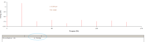
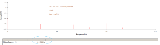
-106dB ---------------------------------> -89dB, it should not affect THD much.
8Ohm vs. 2 way dummy load
🙄
I haven’t simulated that. I saw your simulation. I am probably wrong on that point.-106dB ---------------------------------> -89dB
8Ohm vs. 2 way dummy load

"Offene Schleife => Leerlaufverstärkung"
 This gives you omega and then you can equate R4 (or RA + RB||RC) with jOmega * L. Unfortunately, this still does not solve the "so-called bias problem". Namely VBaseBase' or V(BC) if you prefer.
The correct solution is not so obvious, as McLoughlin pointed out back in the 1970s.
kindly,
HBt.
The correct solution is not so obvious, as McLoughlin pointed out back in the 1970s.
kindly,
HBt.
I'm so sorry, but if the "Dumper" was the yellow of the egg, and above all as simple as our /your blameless-error-canceling simulation would have us believe, then I would only wind 14 windings over a 6mm core ... A Douglas Self approach plus a single air-core coil of around 4.7µH ... and so on. Done.
The user @wahab has not insisted here (in the parallel thread) without reason. And I don't believe in miracles anyway, so much better than 0.03% in actual practice.
#
A loudspeaker is simply not a static load, and stationary conditions do not interest ( interest us in various stages of development - but) the loudspeaker.
HBt.
😢
Final version.
View attachment 1389892
I have some superficial questions~
1. If I can't simulate an existing amplifier, how do I measure the bandwidth? Input a small signal to the amplifier, measure the output, and observe at what frequency the gain of the amplifier decreases to 0?
2. If a 0.1uf capacitor is connected in parallel on resistor R7, will it affect the normal operation of error correction?
3. How to place 0.1R+0.1uF? Place it to the left or right of L1 (4.7uH)?
Thank you so much

You have to know the schematics of the amp to do the mod. Knowing the schematics, you can calculate the loop-gain bandwidth without simulation. I don't recommend to sweep frequency response without knowing the schematics. There might be input filter which can easily give you false reading.1. If I can't simulate an existing amplifier, how do I measure the bandwidth? Input a small signal to the amplifier, measure the output, and observe at what frequency the gain of the amplifier decreases to 0?
Just a resistor. Cap will make it worse.2. If a 0.1uf capacitor is connected in parallel on resistor R7, will it affect the normal operation of error correction?
If you really want to know how it works, you might be interested in this paper. It is the same principle.
https://www.diyaudio.com/community/attachments/current-dumping-analysis-pdf.1386102/
How to calculate the feedforward resistor value.
I would say, just remove 0.1R+0.1uF. If you really want to keep them, put them at the speaker side of the inductor.3. How to place 0.1R+0.1uF? Place it to the left or right of L1 (4.7uH)?
Nî hâo @zergxiaIf I can't simulate an existing amplifier, how do I measure the bandwidth? Input a small signal to the amplifier, measure the output, and observe at what frequency the gain of the amplifier decreases to 0?
we distinguish between the open and the closed loop, as well as between several intersection points in the Bode diagram (note: Bode means that the representation is normalised).
If you are looking for the -3dB points in your amplitude-frequency response in order to calculate the bandwidth of your amplifier, you can do this very easily using a sine wave signal and an oscilloscope.
However, there will definitely be a bandwidth limitation on the input side of the circuit, a classic first-order low-pass filter.
What jxdking means is something else, quite classically, if the amplifier in question were an LM741 opamp, the GBW product or Vuo (the open loop gain) and the cut-off frequency would already be completely sufficient for you. Now all you would need is a piece of paper, a pencil and a ruler ... mental arithmetic or a pocket calculator.
jxdking is looking for the so-called transit frequency, which is the point of intersection with the x-axis at Vu = 1 or 0dB. In the open loop, the omnidirectional /global negative feedback is missing, it is not involved ..! And therefore the desire to record this plot using measurement technology is not entirely trivial.
Please take the advice of an old (but still not wise) man: forget about this pseudo current dumper procedure - nothing is mature here yet.
Tschüß,
HBt.
😊If a 0.1uf capacitor is connected in parallel on resistor R7, will it affect the normal operation of error correction?
Then jxdking s triangle no longer works (well) at all.
0.01kOhm: 10Ohm plus 100nFHow to place 0.1R+0.1uF?
?
That's a very good question, which brings us back to my favourite topic of contention, the stability criterion - and the real behaviour of a feedback system in 4Q operation under real load conditions.
Far right, directly to the output terminals, i.e. parallel to the LS ... that could ... or not!?
Last edited:
Hallo hbtaudioNî hâo @zergxia
we distinguish between the open and the closed loop, as well as between several intersection points in the Bode diagram (note: Bode means that the representation is normalised).
If you are looking for the -3dB points in your amplitude-frequency response in order to calculate the bandwidth of your amplifier, you can do this very easily using a sine wave signal and an oscilloscope.
However, there will definitely be a bandwidth limitation on the input side of the circuit, a classic first-order low-pass filter.
What jxdking means is something else, quite classically, if the amplifier in question were an LM741 opamp, the GBW product or Vuo (the open loop gain) and the cut-off frequency would already be completely sufficient for you. Now all you would need is a piece of paper, a pencil and a ruler ... mental arithmetic or a pocket calculator.
jxdking is looking for the so-called transit frequency, which is the point of intersection with the x-axis at Vu = 1 or 0dB. In the open loop, the omnidirectional /global negative feedback is missing, it is not involved ..! And therefore the desire to record this plot using measurement technology is not entirely trivial.
Please take the advice of an old (but still not wise) man: forget about this pseudo current dumper procedure - nothing is mature here yet.
Tschüß,
HBt.

Thanks jxdking, thanks hbtaudio.
I was attracted by the interesting nature of the subject. Its circuit structure is so simple that it aroused my curiosity.
Is it possible to retrofit an existing amplifier to test error correction? Haha, that's why I focus on the topic

A test? Yes.Is it possible to retrofit an existing amplifier to test error correction?
Success? Very, very unlikely.
I've been following this with great interest and I've already learned a lot. But the obvious question is still burning in my mind: Why? It seems to be a common conception that you can get a blameless architecture amplifier down into the 0.005% THD range and below quite easily just by careful components selection and with very modest bias currents. What's broken that we're trying to fix with this?
Mr. Douglas Self seems to be responsible for the synonym of the blameless concept (and the small details of the topology known since time immemorial), which is why I always refer to him in this regard - and he explicitly writes that it will be very difficult in reality (apart from PC-supported simulation) to actually achieve the promise of 1m% THD.
As you rightly say, many things are necessary for this, including careful matching and the selection of components, but also the layout - simply everything counts.
For followers of the THD less than 0.0005% sect, I no longer call this blameless, but “utopian THD”. All of this is based on everyday reality, not on theoretical feasibility.
HBt.
As you rightly say, many things are necessary for this, including careful matching and the selection of components, but also the layout - simply everything counts.
For followers of the THD less than 0.0005% sect, I no longer call this blameless, but “utopian THD”. All of this is based on everyday reality, not on theoretical feasibility.
Absolutely nothing. It's just seemingly academic gimmicks or finger exercises - for me something like a booster shot.What's broken that we're trying to fix with this?
HBt.
And there's nothing wrong with that. I'm learning a lot from reading your friendly banter back and forth.Absolutely nothing. It's just seemingly academic gimmicks or finger exercises - for me something like a booster shot.
i get this and I'm not aiming for anything close to that. As a beginner, what I like about the blameless architecture is that it's very forgiving. Unless you do something extremely stupid, the result is going to be a decent amplifier. You may have seen the blameless-inspired design I posted here a few days ago. It came out sounding great even though I barely know what I'm doing. 🙂 But a perfect "almost zero" THD amp it ain't.For followers of the THD less than 0.0005% sect, I no longer call this blameless, but “utopian THD”. All of this is based on everyday reality, not on theoretical feasibility.
- Home
- Amplifiers
- Solid State
- Feedforward Error Canceling with Blameless Topology