Hi @hbtaudio, it is the same principle as the current dumping that the dumper has some bias. You don’t need another theory to explain that.
In the post #6, the miller cap and the feedforward resistor aren’t tied together. However, as long as the driver stage works in class A, the distortion would still be low. We can just use the driver stage to drive the feedforward resistor. Thus the amp has 2 outputs. One is the low distortion class A output, the other is the class B/AB final stage. If you can find the optimal value of the resistor by given the inductor, the distortion from the final stage can be canceled out. The overall performance is dominated by the class A stage.
In the post #6, the miller cap and the feedforward resistor aren’t tied together. However, as long as the driver stage works in class A, the distortion would still be low. We can just use the driver stage to drive the feedforward resistor. Thus the amp has 2 outputs. One is the low distortion class A output, the other is the class B/AB final stage. If you can find the optimal value of the resistor by given the inductor, the distortion from the final stage can be canceled out. The overall performance is dominated by the class A stage.

R5 => RA
R3 => RB
R4 => RC
R3 => RB
R4 => RC
1 common output node and 2 ri, one depand ...Thus the amp has 2 outputs.
And the OLG, also the amount of negativ feedback.The overall performance is dominated by the class A stage.
Old Spice ...

To put the concept to the test, all source models in my simulation are considered ideal, as are the IP and VA stages BJT's ... The result is as expected, namely exactly as the deduction specifies.
THD_1k
-66dB vs. -63dB
THD_10k
-44dB vs. -44dB
P = 25W(RMS)
an impressive result.
tpc
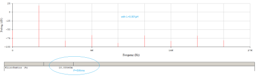
Psst without L means: short L, a completely negligible inductance, simply that of the connecting conductor track.
To put the concept to the test, all source models in my simulation are considered ideal, as are the IP and VA stages BJT's ... The result is as expected, namely exactly as the deduction specifies.
THD_1k
-66dB vs. -63dB
THD_10k
-44dB vs. -44dB
P = 25W(RMS)
an impressive result.
tpc
Psst without L means: short L, a completely negligible inductance, simply that of the connecting conductor track.
Attachments

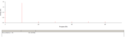

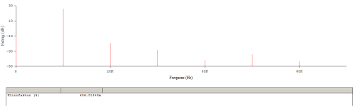
My simulation has over -20dB THD improvement at 10KHz 20Vp.
Imbalanced inductor, 0.1uH.

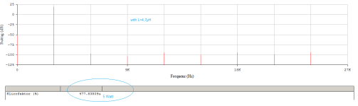
Balanced, with 4.7uH inductor.

@hbtaudio
Here is a run with your resistor values. If your IPS and VAS are identical to mine, the THD discrepancy between you and me may be the result of different simulation software.

Imbalanced inductor, 0.1uH.
Balanced, with 4.7uH inductor.
@hbtaudio
Here is a run with your resistor values. If your IPS and VAS are identical to mine, the THD discrepancy between you and me may be the result of different simulation software.

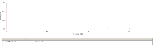
That is possible, I (gladly) use PSPICE from 1995, a win32 version. But I'm only interested in the difference, not the absolute value of the THD.Here is a run with your resistor values. If your IPS and VAS are identical to mine, the THD discrepancy between you and me may be the result of different simulation software.
|3| dB is the largest difference on the credit side is L=4.7µH compared to L=0.001µH (all without ESR, quasi a short).
I think we can say that, of course, the version with L has slightly better THD values, but in reality these will have no significance compared to a correctly dimensioned Self blamesless structure.
The theoretical proof of a marginal possibility of improvement has been provided. Done. A practical setup will have to provide the final proof of resounding effectiveness.
Nevertheless, it was a nice excursion.
greetings,
HBt.
Psst I will check the /my OLG soon. In my simulations, the EF2 is already complete, optimally biased ..!
It is the same as yours, with the exception that all BJTs here are ideal. I will gladly change this so that my values are directly comparable with yours. What I wanted was a comparison with L and with L shorted.@hbtaudio , could you share the full schematics?
Your circuit reminds me too much of a well-known Elektor publication from the early 1970s, in the back of my mind I have the circuit that the designer named after his son.
tpc
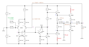
For further simulations, I have stored this schematic as a model.
I had mistakenly transformed your triangle 22 - 36 - 36 with 39 ohms instead of 36 ohms, but this will certainly not be so decisive. Rather, the pair 2N3055 & 2N2955 will now also cause a little noticeable transfer x-over distortion in the spectrum.

I am curious.
😉
I had mistakenly transformed your triangle 22 - 36 - 36 with 39 ohms instead of 36 ohms, but this will certainly not be so decisive. Rather, the pair 2N3055 & 2N2955 will now also cause a little noticeable transfer x-over distortion in the spectrum.
I am curious.
There is the MC12 64-Bit wonder ...Some years ago evebody used LTspice as simulatotor here in this forum, why not anymore?
😉
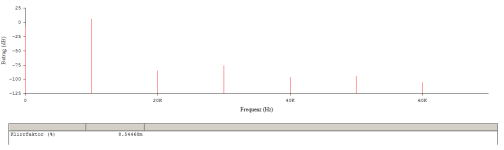
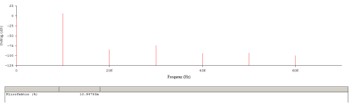
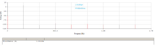
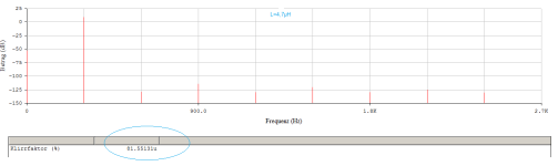
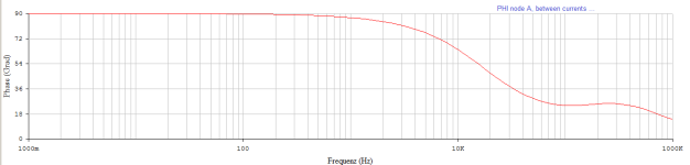
Now that we have a practical model, we can marvel at the miracle of error correction at node A (the current summation):
n=9
f0 = 300Hz, 3kHz
P=500mW, 5W
n=9
f0 = 300Hz, 3kHz
P=500mW, 5W
Attachments

@jxdking
I have to congratulate you, it's hard to believe, but it's true ..!
-100dB vs. -122dB
|22dB|
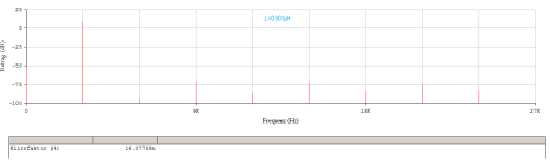
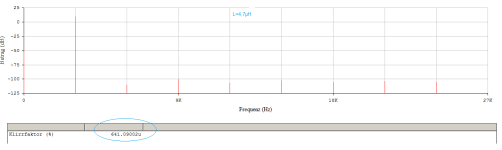
-76dB vs. -104dB
|28dB|
-80dB vs. -106dB
|26dB|
The strange error correction leads to an 18.5-fold improvement in the overall distortion factor. Expressed as a more tangible marker, the standard value of 0.03% improves to a rounded 0.002%.

Not a bad number at all. Who will now carry out the final, practical test and proof? Not me - I've done enough work now.

I have to congratulate you, it's hard to believe, but it's true ..!
-100dB vs. -122dB
|22dB|
-76dB vs. -104dB
|28dB|
-80dB vs. -106dB
|26dB|
The strange error correction leads to an 18.5-fold improvement in the overall distortion factor. Expressed as a more tangible marker, the standard value of 0.03% improves to a rounded 0.002%.
Not a bad number at all. Who will now carry out the final, practical test and proof? Not me - I've done enough work now.
Why are no amplifiers built and sold commercially using this approach?
The trick is only the use of a 4µ7 coil ... 🙄
The trick is only the use of a 4µ7 coil ... 🙄
I would blame the bad branding term “Current Dumping”. Talking about “Current Dumping”, people assume it has a dumper (final stage) without any bias. To most people, no bias means inherently low performance. Only a few people would read the actual paper.Why are no amplifiers built and sold commercially using this approach?
The trick is only the use of a 4µ7 coil ... 🙄
Quad 405 uses 3uH inductor. Larger inductor allows you use larger feedforward resistor. It puts less load to the small Class A stage. I haven’t looked into how much the inductor affects the THD with a real speaker yet.
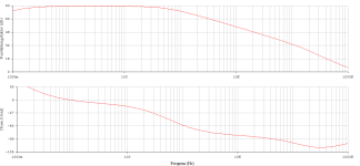
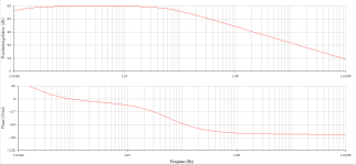
Unfortunately,
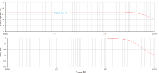
I have to admit to a (not insignificant) mistake. I should have noticed it immediately, but now I'm correcting it: OLG > 100dB, otherwise the almost utopian THD would not have been possible.
What is left to summarize?
This model amplifier (from jxdking and hbt.audio) follows the so-called current dumper predicate pretty much exactly. Wherever the C should be in reality doesn't matter, even the term bridge is slightly misleading. If you are interested in a rudimentary functional description, you can read JLH's article or Baxandall - in the Wireless World journal. The operating principle is very simple - only 14 windings are required ..!
HBt.
Attachments
I also stumbled across this point last night, we should catch up on these missing simulations (soon).I haven’t looked into how much the inductor affects the THD with a real speaker yet.
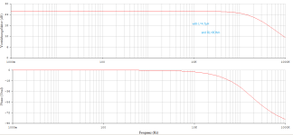
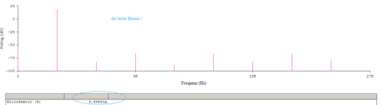
Here is the very last proof (for the transformation and the correction principle) ..!
P=5W(RMS), THD3k= -80dB

P=5W(RMS), THD3k= -80dB
identical, QED-80dB vs. -106dB
|26dB|
Attachments
- Home
- Amplifiers
- Solid State
- Feedforward Error Canceling with Blameless Topology