Feedforward Error Canceling, in theory, could cancel most of the distortion. You could get 0.002% THD figure without much efforts with this technique, at least in simulation. A good example is the famous Current Dumping. If you don't know how Current Dumping works, I highly recommend you jump to this thread to learn how it works and what it can achieve. Current Dumping with OPAMP
Besides Current Dumping, the same technique, Feedforward Error Canceling, can also be implemented to other topology. Here I use a Blameless style amp for example.
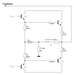
See the example below, the Blameless style with EF2, with an average loop gain. Pretty common setup. Please ignore C1 and R7 for now. They will be used later. The idle bias is at 136ma. 10KHz 20Vp into 8 Ohm is about -72 dB THD.

To implement Feedforward Error Canceling, you need pull a resistor from Miller cap VAS side to the inductor speaker side. However, the VAS doesn't have the capability to drive the feedforward resistor directly. The work around is to create TMC (Transitional Miller Compensation) around the driver stage, and use driver stage to drive the feedforward resistor. See updated circuit below. R13, R4, C1 create a transitional network for the Miller compensation.
From the simulation, you can see all the distortion is gone!!.
The optimal value of R7 depends on the inductor value and also the loop gain bandwidth of the amp. The loop gain bandwidth of the example below is about 600KHz. Thus, the optimal value of R7 should be 2 * pi * Bandwidth * L = 2 * 3.14 * 600,000 * 4.7e-6 = 18 Ohm. If you still don't know what is going on, please search Current Dumpling and learn it. This technique is highly effective but also overlooked.

[EDIT]
PS: In the example above, there are 2 things going on. One is TMC, the other is the feedforward error canceling. They both contribute to lower the THD. The TMC may cause other stability issue. I recommend to check the final version that is without the TMC.
Besides Current Dumping, the same technique, Feedforward Error Canceling, can also be implemented to other topology. Here I use a Blameless style amp for example.
See the example below, the Blameless style with EF2, with an average loop gain. Pretty common setup. Please ignore C1 and R7 for now. They will be used later. The idle bias is at 136ma. 10KHz 20Vp into 8 Ohm is about -72 dB THD.
To implement Feedforward Error Canceling, you need pull a resistor from Miller cap VAS side to the inductor speaker side. However, the VAS doesn't have the capability to drive the feedforward resistor directly. The work around is to create TMC (Transitional Miller Compensation) around the driver stage, and use driver stage to drive the feedforward resistor. See updated circuit below. R13, R4, C1 create a transitional network for the Miller compensation.
From the simulation, you can see all the distortion is gone!!.
The optimal value of R7 depends on the inductor value and also the loop gain bandwidth of the amp. The loop gain bandwidth of the example below is about 600KHz. Thus, the optimal value of R7 should be 2 * pi * Bandwidth * L = 2 * 3.14 * 600,000 * 4.7e-6 = 18 Ohm. If you still don't know what is going on, please search Current Dumpling and learn it. This technique is highly effective but also overlooked.
[EDIT]
PS: In the example above, there are 2 things going on. One is TMC, the other is the feedforward error canceling. They both contribute to lower the THD. The TMC may cause other stability issue. I recommend to check the final version that is without the TMC.
Last edited:

Current Dumping was an unfortunate name for an imaginative and worthwhile approach.
I seem to recall the implementation that used an unpopular op amp, which didn't help.
Alas... 😎
I seem to recall the implementation that used an unpopular op amp, which didn't help.
Alas... 😎
For opamp implementation, the biggest limitations is the max output current. I would use the forwarding resistor no less than 100 Ohm to reduce the current. That requires very high loop gain bandwidth about 3~4MHz. It is doable with modern fast output transistors that have 30MHz fT. I have explored this in this thread. Current Dumping with OPAMPI seem to recall the implementation that used an unpopular op amp, which didn't help.
You are certainly right on both counts.Current Dumping was an unfortunate name for an imaginative and worthwhile approach.
I seem to recall the implementation that used an unpopular op amp, which didn't help.
But the promise is so tempting; to let an amplifier (with first class components) that already works perfectly' on its own also eliminate the very last bit of distortion for itself (like the well-known "Schildbürger"). Residual, flat and zero.

Alternatively, inject 100mA into the driver stage and use the driver stage to drive the feedforward resistor. Or you can just use smaller R4 like 20 Ohm.
The transistor works in class A with low distortion. Thus, we don't have to tie the Miller cap with the feedforward resistor together.

I like this version more even it results a little bit more THD. It is very practical when the driver transistor is already on the heatsink. It doesn't tamper with miller cap and VAS. Thus, it won't affect the stability.
The transistor works in class A with low distortion. Thus, we don't have to tie the Miller cap with the feedforward resistor together.
I like this version more even it results a little bit more THD. It is very practical when the driver transistor is already on the heatsink. It doesn't tamper with miller cap and VAS. Thus, it won't affect the stability.
Last edited:
What about into a more realistic speaker load, instead of an 8R resistor?
Such as shown here: https://www.stereophile.com/reference/60/index.html
Such as shown here: https://www.stereophile.com/reference/60/index.html
I will put your question in another way. How much does the output inductor affect the sound?What about into a more realistic speaker load, instead of an 8R resistor?
Such as shown here: https://www.stereophile.com/reference/60/index.html
Here, the inductor is required to make it work.
Conventionally, 1uH should not affect performance at all, because the speaker cable you use may exceed 1uH. 1-5uH, is arguable that it may affect the speaker performance. 4.7uH is the largest value that I would go.
Last edited:
The error cancelling is through the bridge, the feedforward resistor and the inductor. Bridge acts instantly. No feedback is needed.I don't realize /see the necessarily positiv feedback loop for ..!
Whats up with the ESR of the coil L1 = 4µ7H? How many milli ohms are we talking about here?The error cancelling is through the bridge, the feedforward resistor and the inductor. Bridge acts instantly. No feedback is needed.
The load current flows almost exclusively via Q3 up to the point in the instantaneous signal at which the voltage drop at R10 falls below the interlock diffusion voltage of Q10. Only when Vbe has been overcome does Q10 come into play.
But the whole trick here is XL, the frequency-dependent reactance of the tiny coil. If you now short-circuit the coil, to what value will your THD10k rise?
After all, we are looking at 24Wrms, 10kHz, with only 0.002% thd.
Interesting.
Oh,
I just saw you're running the 3055 /2955 combo at just under 800mAdc - as up to 10Wrms in pp A mode.
Sorry, but we can no longer call this scenario current dumping - error canceling maybe 😉😎.
I just saw you're running the 3055 /2955 combo at just under 800mAdc - as up to 10Wrms in pp A mode.
Sorry, but we can no longer call this scenario current dumping - error canceling maybe 😉😎.
The idle bias is less than 130ma. The number you see is the DC component when under load.I just saw you're running the 3055 /2955 combo at just under 800mAdc - as up to 10Wrms in pp A mode.
I want to generalize error canceling approach beyond current dumping.
👍 understand.I want to generalize error canceling approach beyond current dumping.
The ESR is not in the consideration. It is zero in the simulation. In real world, it is way smaller than the emitter 0.22 Ohm. There should not be an issue to ignore its ESR.Whats up with the ESR of the coil L1 = 4µ7H? How many milli ohms are we talking about here?
The emitter resistors are inside the feedback loop, the inductor's series resistance is not. Instead of ignoring it, you could correct for it: https://www.diyaudio.com/community/threads/current-dumping-with-opamp.420292/post-7857549
Yes, I missed that perspective.The emitter resistors are inside the feedback loop, the inductor's series resistance is not. Instead of ignoring it, you could correct for it:
It is just a proof of concept. I left out protection, bias, current source implementation.By the way, Q17 and Q18 might go up in smoke during clipping.
Perhaps this drawing will help us to intuitively grasp the situation a little better?
Attachments
Last edited:
Z(jOmega) = 0.0003Ohm + j(2*PI*f * 4.7µH)

The star (R3, R4, R5) is equivalent to the triangle above (R7, R4, R10).
First I calculate an air coil from 0.8mm enameled copper wire, just under 34cm in length should be enough to wrap around a 6mm drill 14 times, from which the DC resistance can now also be calculated -> 0.3mOhm.
Of course, I immediately transform the triangle R4,7,10 into a star. At the same time, I calculate the peak current that Q3 & Q4 alone will probably have to supply to the load before Q7 and Q10 become fully involved -> approx. 23mA pk.
We therefore distinguish between two borderline cases
a) both transistors do not conduct (block) or only marginally, the switches are open
b) both transistors (Q7 and Q10 above) conduct completely, the switches are closed in any case
In case
a) Z adds vectorially to R_feedback, this is also the crossover, the zero crossing, RA (as well as RB and RC) are completely in the gnfb loop
b) now it gets exciting, we have overcome the critical range of the signal zero crossing and the actual output stage switches on in parallel with the other branches, everything is still in negative feedback due to |Z|, everything!
Everything only changes significantly when |Z| exceeds a very specific amount -> now this is added to the internal, dynamic output resistance at the node between the two 0.22Ohm emitter resistors. At 100Hz, this addition (a series resistor, an impedance) is now 0.3Ohm. This frequency-dependent node Z is now opposite the ensemble of RA, RB & RC; two currents now add up vectorially in the output node (R_Load).
At this node, the miracle of the now hopefully erasing error of the zero crossing takes place, only at this point we have long since left it behind by means of the bypass (the bypass of RA and RB or RC), incidentally with the full power of our GNFB.
Bye,
HBt.
😉
Last edited:
- Home
- Amplifiers
- Solid State
- Feedforward Error Canceling with Blameless Topology