Once you realize that some 20% THD is added in the recording / mixing / mastering process, and the average speakers will add some 10% more, a reduction of the cumulative THD from 30.1% to 30.01% looks like an "achievement" that only the most idiotic audio magazines would acclaim.
https://www.youtube.com/watch?v=TKYQ5ibxslI
😕 I'm Sorry, Are you from the past? 😕
If you could make the retur path identical to the forward path, then there would be no inductance as the two currents would cancel the generated magnetic field, if the two are far apart then inductance would be doubled.. So off course return path path is essiental to wire inductance.
This statement troubled me all night..I just realized why you were thinking double.
If you consider the magnetic field energy stored in space as a result of a single wire, you find a problem... If you try to integrate the total energy from the wire surface out to infinity, you find that the energy is infinite. The second conductor return path for the current also has an infinite energy field, but where the two cancel, the inductance becomes bounded, the math problem is solved.
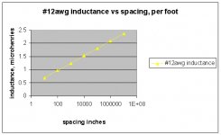
I'll try to dig up another graph..done. This is what the terman equation predicts for extreme wire spacing. Note that on a log scale, it's straight.
I tested the validity of the terman equation for gauges between 30 and 10, with spacings from contact out to 10 inches, from 20 hz out to 50 Khz. Measurement was very close to what terman predicts, I got to within 4% on every measurement, even the tight twist pairs. edit: needless to say, I didn't try a spacing of 10e8 inches..
The recent Q, what is this w/r to feedback speed... has anybody modelled the FB line with it's inductance to signal return, including source and load impedance?
And has anybody considered the coupling to output load currents and the impact on the feedback? To me, one of the more sensitive spots in an amplifier is the feedback path physically and all the things that can affect it. More specifically, how the supply rail currents can couple to the fb loop, as well as how the chassis ground loop currents (from input jack to IEC safety ground) go right by the fb loop.
John
Attachments
Last edited:
😕 I'm Sorry, Are you from the past? 😕
I can't. We just learned that there are no time delays, thus no past.
It's all some phase based trickery.

This statement troubled me all night..I just realized why you were thinking double.
If you consider the magnetic field energy stored in space as a result of a single wire, you find a problem... If you try to integrate the total energy from the wire surface out to infinity, you find that the energy is infinite. The second conductor return path for the current also has an infinite energy field, but where the two cancel, the inductance becomes bounded, the math problem is solved.
I'll try to dig up another graph..done. This is what the terman equation predicts for extreme wire spacing. Note that on a log scale, it's straight.
I tested the validity of the terman equation for gauges between 30 and 10, with spacings from contact out to 10 inches, from 20 hz out to 50 Khz. Measurement was very close to what terman predicts, I got to within 4% on every measurement, even the tight twist pairs. edit: needless to say, I didn't try a spacing of 10e8 inches..
The recent Q, what is this w/r to feedback speed... has anybody modelled the FB line with it's inductance to signal return, including source and load impedance?
And has anybody considered the coupling to output load currents and the impact on the feedback? To me, one of the more sensitive spots in an amplifier is the feedback path physically and all the things that can affect it. More specifically, how the supply rail currents can couple to the fb loop, as well as how the chassis ground loop currents (from input jack to IEC safety ground) go right by the fb loop.
John
This is very reason I use 4 layer boards, it offers the possibility to exchange some inductance for distributed and well damped capacitance. And why my exit terminals and input transistors are placed very close. (I have my mosfet relay included in the loop)
Originally Posted by udok View Post
This hole discussion about feedback misses some important points:
+ What is the time response?
(this does not directly dependent on feedback
except rise time limitations )
Spacial hearing is very sensitive to time response.
Many modern amps are on the edge of stability due to aggressive optimization of THD numbers but ignore good time response.
Best would be a Bessel or Gauss frequency response function of the whole reproduction chain as done in Oscilloscopes.
Nobody does this as magazin reviewers would cry out loud.
Once you realize that some 20% THD is added in the recording / mixing / mastering process, and the average speakers will add some 10% more, a reduction of the cumulative THD from 30.1% to 30.01% looks like an "achievement" that only the most idiotic audio magazines would acclaim.
Have read the thread with great interest, but is confused
Perhaps because of my lack of English skills.
Do not think it's fair to ignore Udok's questions.
I also believe that the delay of the correction signal can be very small and insignificant.
But not always insignificant, it must depend on open loop and clossed loop bandwidth and negative feedback factor. How much signal for the correction comes too late.
I see two places where there can be added delay to the amplifier, the amplifier (open loop) and in the feedback network. ( among other Lead-Lag Compensated)
Delayed depends on several RC component (tau = R*C)
The current negative feedback factor must reduce delay.
But high open-loop gain also limits the bandwidth, it must always be a compromises between all of these factors open-loop, clossed-loop and feedback factor
Since tau= RC is constant and therefore also delayed until the phase shift starts to become noticeable when 180 degrees is reached oscillation is a reality. , Negative feedback will works worse and worse and you see sharp rise in THD in this area of high frequencies.
Delay and bandwidth must be related in some way.
Perhaps everything is explained in the thread, but a quick summary for dummies would be great.
Sergio
In a two pole compensated amplifier which would otherwise be Miller compensation (if we removed the centre resistor) the initial delay is the same as in a Miller compensated amplifier. What happens is that the feedback signal IS delayed (the resistive divider in the feedback arm cannot work faster than the output signal that drives it).
The leading edge of the output signal then rises FASTER than the input signal and then after the initial cycle the delay, I agree, becomes smaller.
This is actually one reason two pole compensated amplifiers "sound strange" I would suggest. The initial transient (delay) is slow (like Miller) and yet the leading edge overcompensates, causing an "artifically bright" sound for the duration of the catch-up period.
If the amplifier is configured to include local "inclusive" feedback it may seem that the feedback is instantaneous. One approach is to connect the VAS collector to the feedback point using a capacitor. This gives a local phase lead compensation (for a classic example see Bailey's 1968 amplifier (Wideband DC coupled power amplifier for Laboratory Service, Electronic Engineering Dec. 1968 pp 688-694); JLH also used this approach in many of his designs). In such a design negative feedback arrives at the feedback point earlier than the signal from the output stage, as the input and VAAS stages tend to be much faster. It may seem that the feedback is instantaneous, whereas it is derived from two origins!
Udok - the delay with feedback is reduced. This is because the bandwidth with feedback is (usually) much faster than without.
Sergio
In a two pole compensated amplifier which would otherwise be Miller compensation (if we removed the centre resistor) the initial delay is the same as in a Miller compensated amplifier. What happens is that the feedback signal IS delayed (the resistive divider in the feedback arm cannot work faster than the output signal that drives it).
The leading edge of the output signal then rises FASTER than the input signal and then after the initial cycle the delay, I agree, becomes smaller.
This is actually one reason two pole compensated amplifiers "sound strange" I would suggest. The initial transient (delay) is slow (like Miller) and yet the leading edge overcompensates, causing an "artifically bright" sound for the duration of the catch-up period.
If the amplifier is configured to include local "inclusive" feedback it may seem that the feedback is instantaneous. One approach is to connect the VAS collector to the feedback point using a capacitor. This gives a local phase lead compensation (for a classic example see Bailey's 1968 amplifier (Wideband DC coupled power amplifier for Laboratory Service, Electronic Engineering Dec. 1968 pp 688-694); JLH also used this approach in many of his designs). In such a design negative feedback arrives at the feedback point earlier than the signal from the output stage, as the input and VAAS stages tend to be much faster. It may seem that the feedback is instantaneous, whereas it is derived from two origins!
Udok - the delay with feedback is reduced. This is because the bandwidth with feedback is (usually) much faster than without.
Now I am really disappointed in your explanation!
Have you tried listening to a two-pole amp?
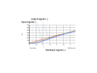
The effect is shown in the simulations, and also appears as an overshoot in an AC frequency analysis.
Red line- input; green line- (delayed) output; blue line- measured at the feedback point.
Almost all my amps are with two-pole compensation VFA and CFA, and I like the sound.
That overshoot in an AC analysis is characteristics for a VFA two-pole compensation and can be simply corrected, but not needed, nothing to do with bad sound. You just show some plots an say it is something, not good enough for me.
Sadly (for naive thinking) they are not related at all. A long piece of cable has a significant delay but wide bandwidth. A low pass filter has narrow bandwidth but negligible delay. Hence, proof by construction that delay and bandwidth are unrelated.thor2 said:Delay and bandwidth must be related in some way.
Damir, you wasting your time with arguing like this. Just ignore it.
Yes Pavel I know that, just can't keep my mouth shut, sometime.
Sadly (for naive thinking) they are not related at all. A long piece of cable has a significant delay but wide bandwidth. A low pass filter has narrow bandwidth but negligible delay. Hence, proof by construction that delay and bandwidth are unrelated.
 good example
Sergio
In a two pole compensated amplifier which would otherwise be Miller compensation (if we removed the centre resistor) the initial delay is the same as in a Miller compensated amplifier. What happens is that the feedback signal IS delayed (the resistive divider in the feedback arm cannot work faster than the output signal that drives it).
The leading edge of the output signal then rises FASTER than the input signal and then after the initial cycle the delay, I agree, becomes smaller.
This is actually one reason two pole compensated amplifiers "sound strange" I would suggest. The initial transient (delay) is slow (like Miller) and yet the leading edge overcompensates, causing an "artifically bright" sound for the duration of the catch-up period.
If the amplifier is configured to include local "inclusive" feedback it may seem that the feedback is instantaneous. One approach is to connect the VAS collector to the feedback point using a capacitor. This gives a local phase lead compensation (for a classic example see Bailey's 1968 amplifier (Wideband DC coupled power amplifier for Laboratory Service, Electronic Engineering Dec. 1968 pp 688-694); JLH also used this approach in many of his designs). In such a design negative feedback arrives at the feedback point earlier than the signal from the output stage, as the input and VAAS stages tend to be much faster. It may seem that the feedback is instantaneous, whereas it is derived from two origins!
Udok - the delay with feedback is reduced. This is because the bandwidth with feedback is (usually) much faster than without.
Hi Jonh, this is " déjà vu " , I have already make that simulation and is in post #36, in post #38 Jan Didden pointed out that this type of impulse has a lot of HF energy and propose adding a filter at the input of amplifier and that is on post #40 ,
Dont forget that music are slow, and with normal music the two pole compensation amplifier will never do that phenomenon, there is no catch-up period.
But the two pole compensation amplifier is not for people that enjoy listening to square waves 🙂 ,there is overshoot that always sound bad in the oscilloscope. 🙄
now seriously, I would be interesting in see the type of compensation you use. can you show a circuit? Thanks.
Hi mr. Pavel Macura ,
I have see some amplifier designed by you, and they dont have the indutor at output, why you dont use them?
I have see some amplifier designed by you, and they dont have the indutor at output, why you dont use them?
Damir, you (are) wasting your time with arguing like this.
That could be more widely applied.
And has anybody considered the coupling to output load currents and the impact on the feedback? To me, one of the more sensitive spots in an amplifier is the feedback path physically and all the things that can affect it. More specifically, how the supply rail currents can couple to the fb loop, as well as how the chassis ground loop currents (from input jack to IEC safety ground) go right by the fb loop.
John
John can you develop a bit more this issue. I would like a lot to hear your opinion about solutions to minimize the impact of these two problems.
Distortion In Power Amplifiers
5.5 DISTORTION 5: Decoupling errors.
Most amplifiers incorporate small electrolytics (10 - 220uF) between each rail and ground to ensure HF stability. As a result rail-voltage variations cause current to flow into the ground.
If an unregulated power supply is used, (and there are almost overwhelming reasons for doing so) the rails have non-zero AC impedance and bear voltage variations due to amplifier load currents as well as 100Hz ripple. In Class-B, the supply-rail currents are halfwave- rectified sine pulses, and if they contaminate the signal then distortion is badly degraded. The usual route for intrusion is via decoupling grounds shared with input or feedback networks, and a separate decoupler ground back to the star point is usually a complete cure.(Note that the star-point should be defined on a short spur from the heavy connection joining the reservoirs; using B as the star point introduces hum due to the large reservoir-charging current pulses passing through it)
Fig 27 shows the effect on an otherwise Blameless amplifier handling 60W/8-Ohm, with 220uF rail decouplers; at 1kHz distortion has increased by more than ten times, which is quite bad enough. However, at 20Hz the THD has increased 100-fold, turning a very good amplifier into a profoundly mediocre one by one misconceived connection.
Fig 27
5.6 DISTORTION 6: Induction from supply rails.
Like Distortion 5, this stems directly from the Class-B nature of the output stage. The supply-rail currents are halfwave-rectified sine pulses, which can readily crosstalk into sensitive parts of the circuit by induction. This is very damaging to the distortion performance; Fig 28 shows a large extra distortion component rising at about 6dB/octave. The distortion may intrude into the input circuitry, the feedback path, or even the output cables.
Fig 28
This inductive effect was first publicised by Cherry [17], though the effect has been recognised by some practitioners for many years.[18] This effect, apparently unfamiliar to most designers, seems to be a widespread cause of unnecessary distortion.
The contribution of Distortion 6 can be reduced below the noise floor. Firstly, rigorously minimise loop areas in the input and feedback circuitry, ie keep each signal line very close to its ground. Secondly, limit the ability of the supply wiring to establish magnetic fields in the first place, by minimising the area of circuit loops carrying half- wave pulses.
5.7 DISTORTION 7: NFB Takeoff point distortion.
There is a subtle trap in applying global NFB. Class-B output stages are awash with large halfwave-rectified currents, and if the feedback takeoff point is in slightly the wrong place, these currents contaminate the feedback signal, making it an inaccurate representation of the output voltage, and so introducing distortion; Fig 29 shows the problem.
Fig 29
At these current levels, all wires and PCB tracks must be treated as resistances, and it follows that point C is not at the same potential as point D whenever TR2 conducts. If feedback is taken from D, then a clean signal is established here, but the signal at output point C has a half- wave rectified sinewave added to it, due to the resistance C-D. The output will be distorted but the feedback loop does nothing about it as it does not know about the error. Fig 30 shows the practical result for an amplifier driving 100W into 8-Ohm. The resistive path C-D that did the damage was a mere 6mm length of heavy-gauge wirewound resistor lead.
To eliminate this distortion is easy, once you are alert to the danger. Taking the NFB feed from D is not advisable as D is not a mathematical point, but has a physical extent, inside which the current distribution is unknown. Point E on the output line is much better, as half-wave currents do not flow through this arm of the circuit.
•17] Cherry, E "A New Distortion Mechanism In Class-B amplifiers." JAES May 1981, p237. (Inductive distortion)
- Status
- Not open for further replies.
- Home
- Amplifiers
- Solid State
- Feedback loop speed