As I said a TPC amplifier can have less than a 1nS at AUDIO FREQUENCY, audio frequency,
what is so difficult to understand that audio frequency have low slew rate and as long as phase between in and out is near zero the delay is near zero, feedback helps to improve phase, if you have a lot of loop gain at audio frequencies you will have very low delay.
Of course at higher frequency the delay will be bigger, but this is a forum about AUDIO.
You don´t have even to be that smart to understand this.
The problem is that you dont understand that a linear amplifier has near zero propagation delay.
switch on your brain and think why comparators have propagation delay in the specifications and OPAMP does not.
switch on your brain and think why comparators have propagation delay in the specifications and OPAMP does not.
Delay is *independent* of frequency. Or do you think that a 1khz signal travels faster than a 10 kHz signal?
If this would be the case i could not transmit a clean rectangle pulse over an amp.
The faster frequency components would have a different delay
than the slower ones and the output would be distorted.
A straight piece of 20cm wire has 1 ns seconds of delay.
An audio amp with its capacitors and transistor storage times is much slower.
Maybe you confuse phase shift with real physical time delay?
Then you could even have negative phase shift...
and the signal could be at the output even
before it arrives at the input... strange, isn't it?
What have comparators to do with audio amplifiers?
i don't now - maybe you can explain this too...
It seems to me that this is more and more esoteric talking than engineering.
BTW, i don't have a problem! But i don't like this kind of fruitless talking.
Last edited:
Delay is *independent* of frequency. Or do you think that a 1khz signal travels faster than a 10 kHz signal?
If you had said that " PROPAGATION Delay is *independent* of frequency. " then yes I would agree with you, Propagation delay or the " real " delay is independent of frequency, but as I said propagation delay is very low in linear amplifiers .
If you inject a 20khz signal in the input of TPC amplifier the same signal will be at output 5nS later, if you put a 300Khz signal at input the signal will take 300nS . Because at 20khz the gain loop of the TPC amplifier is higher, and the current needed to charge and discharge the miller cap is much lower, please investigate better before you talk about something.
And if you think that using a electronic simulator like the LTspice to prove something is esoteric talk, then you have a real problem.
Great that we finally can find a common wording 🙂
Propagation delay is the thing that has real physical meaning as it describes the speed at which energy and information is transported.
And unfortunately it is not as small as you think as it is related to 1/bandwidth.
You can test this by looking at the pulse response.
Your simulations are not of much use as you look at the STEADY state.
In the simulation you switch on an ideal sinus at the time before the Big Bang
and hope to describe something meaningful...
But Audio is about CHANGES in signal which your simulations completely neglects.
I guess next time you tell me that an LC tank circuit is a better amp
as it has even less phase shift than your resonant Two Pole compensation...
A straight piece of 20cm wire has 1 ns seconds of delay.
Actually, a piece of wire by itself cannot have any delay associated with it, there is a return conductor required.
The prop velocity of a pair of conductors will rely on the distributed L and C, which is dependent on how the two conductors relate to each other geometrically.
edit: The settling time will depend also on the source and load impedance in relation to the line.
John
Last edited:
Udok, how much propagation delay you predict there is in a linear amplifier? 500nS 1uS ? What is the approximate value ?
@30 KHz i see 7 ns difference, on The gain-phase plot i have 2.5 degree phaseshift.
@1KHz The difference is down to 3ns and there's no phase shift on the gain-phase plot
3 nanoseconds is a whole lot of MHz..
Feedback works in tiny tiny increments of an extremely short duration, so you'll never get anything transient through the amplifier as music signals, because the change is so tiny and feedback so fast you'll newer overshoot the OLG, but off course as the accumulated signal level goes towards the limits you loose loop gain and thus get less precision. This is also kind of an answer to Jan's initial question
Actually, a piece of wire by itself cannot have any delay associated with it, there is a return conductor required.
The prop velocity of a pair of conductors will rely on the distributed L and C, which is dependent on how the two conductors relate to each other geometrically.
edit: The settling time will depend also on the source and load impedance in relation to the line.
John
Strictly speaking this too is not correct
 ... If there is no return wire the electromagnetic field is happy to propagate into the air... its called antenna.
Strictly speaking this too is not correct
Hmm, how best to explain..
The prop velocity along a wire is entirely dependent on the inductive and capacitive characteristics of the wire on a per unit length basis. Do not confuse E/M field propagation with propagation along the wire.
To state that a single wire has a prop velocity is actually incorrect, as it is only part of the system. It's like saying a foot long length of wire has an inductance of 1 uH. It does not.
A cylindrical wire does have an internal inductance of 15 nH per foot at low frequency, a consequence of physics as defined by some dead guys a while ago. But it cannot be given an external inductance until the path of return current is known.
Within the context of the present discussion, a single wire prop delay is meaningless with no definition of the current return path. AND, the feedback current/voltage at the input difference "engine" (input pair) has further "issues" as well. I explain..
For an arbitrary pc design with the feedback path in copper, the total loop inductance will depend on the geometry of the loop and where the FB current returns. The response of the FB loop AT the input pair also depends on the load at the input pair, the inductance of the loop, the capacitance, and the output node impedance.
If I were trying to work it out, I'd go lumped element on the FB loop, and include about 1 uH as the parasitic inductance from output to the divider, I would suspect trace capacitance is unimportant..Perhaps someone can do that modelling? Oh, don't forget to include the pass through characteristics of the divider resistor attached to ground, it has mutual coupling considerations as well. Oh, and layout considerations between the feedback wire/return path and it's coupling to the output stage currents. Many designers fail to consider the massive design difference between old high impedance tubers and low impedance sand parts..
To inject a wire as an antennae, one also has to consider the wavelength as well as the coupling of the wire to a 377 ohm external environment.. end to end resonance or half resonance of a 1 foot wire kinda requires frequencies just a tad above my hearing range.. Kinda, as in 5 orders of magnitude..😀
John
If you could make the retur path identical to the forward path, then there would be no inductance as the two currents would cancel the generated magnetic field, if the two are far apart then inductance would be doubled.. So off course return path path is essiental to wire inductance.
Udok, how much propagation delay you predict there is in a linear amplifier? 500nS 1uS ? What is the approximate value ?
I can remember something about 1 / (pi * bandwidth).. for a typical audio
amp with 200kHz bandwidth this is about 1.6 us.
It is logical if you think about it. The fastest signal change is proportional
to the rise time of a 200 kHz sine.
Many amps have some dead-time too ( storage time in semiconductors = they are not minium-phase systems), but this may be negligable in audio.
In LTSpice a plot of group-delay (instead of phase) in conjunction with frequency response would often be more meaningful.
But i know of no way to enable this easily.
This hole discussion about feedback misses some important points:
+ What is the time response?
(this does not directly dependent on feedback
except rise time limitations )
Spacial hearing is very sensitive to time response.
Many modern amps are on the edge of stability due to aggressive optimization of THD numbers but ignore good time response.
Best would be a Bessel or Gauss frequency response function of the whole reproduction chain as done in Oscilloscopes.
Nobody does this as magazin reviewers would cry out loud.
Digital Audio is optimized for frequency response and
not for good time response. You see this if you try to record and play back a rectangle pulse => lots of ringing due to steep filters.
+ What is the behaviour in case of overload?
(this is often worse with feedback systems):
clipping behaviour, long overload recovery times,
shifting of quiescent operating point due to unsymetrical heating...
This minor details maybe distinguish good amplifiers from excellent ones in my opinion.
If you could make the retur path identical to the forward path, then there would be no inductance as the two currents would cancel the generated magnetic field,
While correct, it has caveats. A coaxial cable almost does exactly that, by making the current centroids occupy the exact same place in space, that being the center of the coax. Any two conductors however, cannot do that without short circuit. note:my avatar shows the magnetic field distribution between the core and shield conductors of a coax. Nothing external, and at frequency, nothing internal to the core due to skinning.
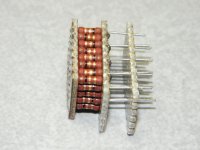
For my sub nanohenry resistors, I do exactly what you say, but I do so by distributing the current through two arrays of interleaved resistors. While there is still magnetic field, the total stored energy is drastically reduced.
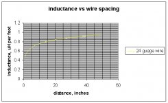
Well, almost. If you use the terman equation, you can see how the return path changes the inductance.. Not doubling, its some kinda log relationship. Oh, btw..my graph does NOT include the enhancement caused by a short loop length to width ratio. There is further enhancement caused by the morphing to a solenoidal design, my graph is for a per foot calculation on long runs.if the two are far apart then inductance would be doubled.. So off course return path path is essiental to wire inductance.
John
Attachments
Last edited:
I hope that we do not forget that velocity of propagation depends on coax cable dielectrics
Coax Velocity Factor | Coaxial Cable Velocity Factor | Radio-Electronics.com
Regardless that, I do not understand what is the point of this thread.
Coax Velocity Factor | Coaxial Cable Velocity Factor | Radio-Electronics.com
Regardless that, I do not understand what is the point of this thread.
@30 KHz i see 7 ns difference, on The gain-phase plot i have 2.5 degree phaseshift.
@1KHz The difference is down to 3ns and there's no phase shift on the gain-phase plot
3 nanoseconds is a whole lot of MHz..
Feedback works in tiny tiny increments of an extremely short duration, so you'll never get anything transient through the amplifier as music signals, because the change is so tiny and feedback so fast you'll newer overshoot the OLG, but off course as the accumulated signal level goes towards the limits you loose loop gain and thus get less precision. This is also kind of an answer to Jan's initial question
With your logic a rising frequency response (or tiny resonance) would produce NEGATIVE delay times. This is physically impossible, as my teacher told me...
And how often will you reproduce this crude digital feedback approximation again?
This is crude as it does not consider phase delay... but delay is important... it is the Om of feedback.
Even better: If you are clever you could build amps which work with POSITIVE feedback. They have the potential to not only reduce distortion but to mathematically extinguish it.
Last edited:
While correct, it has caveats. A coaxial cable almost does exactly that, by making the current centroids occupy the exact same place in space, that being the center of the coax. Any two conductors however, cannot do that without short circuit. note:my avatar shows the magnetic field distribution between the core and shield conductors of a coax. Nothing external, and at frequency, nothing internal to the core due to skinning.
For my sub nanohenry resistors, I do exactly what you say, but I do so by distributing the current through two arrays of interleaved resistors. While there is still magnetic field, the total stored energy is drastically reduced.
Well, almost. If you use the terman equation, you can see how the return path changes the inductance.. Not doubling, its some kinda log relationship. Oh, btw..my graph does NOT include the enhancement caused by a short loop length to width ratio. There is further enhancement caused by the morphing to a solenoidal design, my graph is for a per foot calculation on long runs.
John
John, I assume distance = conductor length in your graph below, not conductor spacing which I take as 24 AWG.
For my sub nanohenry resistors, I do exactly what you say, but I do so by distributing the current through two arrays of interleaved resistors. While there is still magnetic field, the total stored energy is drastically reduced.
John
Very interesting... Could you explain this in more detail?
John, I assume distance = conductor length in your graph below, not conductor spacing which I take as 24 AWG.
X axis is physical distance between the two parallel conductors. It can never be less than the diameter of a 24 awg wire in that graph. My apologies for not labelling the graph very clearly. I had trouble even finding it on my computer, it was from 2006.
If you have one coil and put current in it, you get an inductance. If you have two coils and put half the current in each, you get half the overall stored energy, so the system inductance is half..Very interesting... Could you explain this in more detail?
E = 1/2 L I^2. Half current is quarter stored energy.
If you take cat5e and measure the inductance of one pair shorted at the end, say ten feet long, you get an inductance. If you parallel a second pair in the cable, the inductance will be half one pair. If you parallel all four, the inductance will be one quarter.
If you could see the currents in the 4 pairs, you would see that overall the current is being cancelled because it's going through itself. The more cables you parallel, the lower the overall inductance becomes.
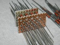
Now do the same with resistors..Here's a pic of one being assembled. Think of the current directions as per a chessboard, red one direction, black the other. In fact, I oriented the resistor markings to give a better picture of how the resistors connect. The perf on the far right, note that only half the leads go through to there. The center perf is the other connection. edit: oh, forgot. there are 40 resistors there.
The beauty of this is you can use two different values to create a divider, and there will be no mutual coupling across the lower value resistor.
I'm using a varient of this for my EDM pulse generator, the series resistor for the spark current limit being one set, the CVR for the current readback the other. nSec response with no circuit inductance or coupling to jam up the scope pics.
Edit: added the second pic to show how half the resistors will be soldered to the middle plate, they are loaded at this stage. I solder them first, clean the leads, then pull the far plate away and load the other half of the resistors. I then solder to the far plate, add the third plate that is missing in this view, and solder the balance of the leads to it.
John
Attachments
Last edited:
in LTspice you can make a .func declaration to use in the waveform viewer:
.func Tg(x) -d(im(log(x)))/2/pi
or you can left click on the right axis in the label region (cursor changes to ruler) and change the plot from phase to group delay in the pop up
and you can always see the group delay at a point in the cursor numeric window with a waveform cursor - and the delta when 2 waveform cursors are active
Last edited:
This hole discussion about feedback misses some important points:
+ What is the time response?
(this does not directly dependent on feedback
except rise time limitations )
Spacial hearing is very sensitive to time response.
Many modern amps are on the edge of stability due to aggressive optimization of THD numbers but ignore good time response.
Best would be a Bessel or Gauss frequency response function of the whole reproduction chain as done in Oscilloscopes.
Nobody does this as magazin reviewers would cry out loud.
.
Once you realize that some 20% THD is added in the recording / mixing / mastering process, and the average speakers will add some 10% more, a reduction of the cumulative THD from 30.1% to 30.01% looks like an "achievement" that only the most idiotic audio magazines would acclaim.
- Status
- Not open for further replies.
- Home
- Amplifiers
- Solid State
- Feedback loop speed