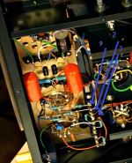
In the picture, three lines are used for feedback by Ken Shind. Number one and two are feedback from output tubes and number 3 from output transformer .local and global .Does anyone have an opinion?
View attachment 1148717
View attachment 1148717
Attachments
Last edited:
it can be anything, but the concept is like this Yves Monmagnon amp:
http://www.dissident-audio.com/PP_ECL86/Page.html
http://www.dissident-audio.com/PP_ECL86/Page.html

zintolo .....local feed back in shindo amp is not dc ...need cap .but pcl86 circuit close to shindo . thanks .
Post # 6 schematic:
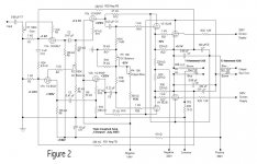
Output Stage Feedback circuits:
Local feedback of the output stage:
Positive feedback from plate 1 to screen 2 (not Ultra Linear)
Positive feedback from plate 2 to screen 1 (not Ultra Linear)
Negative feedback from output transformer plate 1 to cathode 1
Negative feedback from output transformer plate 2 to cathode 2
Local and global negative feedback paths from output stage to:
Positive feedback from output transformer tertiary winding 1 to 12AZ7 1 (Bootstrap)
Positive feedback from output transformer tertiary winding 2 to 12AZ7 2 (Bootstrap)
Negative feedback from plate 1 to: plate 2 of 12BH7 (AC and DC), and grid 2 of 12AZ7 (AC)
Negative feedback from plate 2 to: plate 1 of 12BH7 (AC and DC), and grid 1 of 12AZ7 (AC)
Positive feedback (AC) from output cathode 1 to 12AZ7 cathode 1
Positive feedback (AC) from output cathode 2 to 12AZ7 cathode 2
I hope I got them all, and I hope I got the Positive and the Negative senses of the feedback correct.
If you like Positive feedback, and Negative feedback, this amplifier has it!
(10 feedback loops, or 12 feedback loops depending on how you look at it)
Post your corrections, please?
Last edited:
McIntosh needs an extra gain stage on the front end because half
the output stage gain is used as local nfb.
the output stage gain is used as local nfb.
No UL in Mc Intosh amp; there is a one section on Radiotron where is well explained the basic circuit from Mac, the first version .
Walter
Walter
waltube,
1. Good point about the McIntosh amplifiers.
One tube's plate signal is fed to the opposite tube's screen (that is positive feedback):
Push Plate to Pull Screen.
Pull Plate to Push Screen.
With Ultra Linear, a portion of one tube's plate signal is fed back to the same tube's screen (that is negative feedback).
An amplifier can Not have both McIntosh plate to opposing screen feedback, and at the same time have Ultra Linear feedback.
2. I hope everyone understood my Post # 8.
I said:
"Positive feedback from plate 1 to screen 2 (not Ultra Linear)
Positive feedback from plate 2 to screen 1 (not Ultra Linear)
The key word is "not" Ultra Linear.
Perhaps I should have typed "Not" ultra linear.
All those feedback loops on a single amplifier is making me Loopy. Ha Ha!
What are the benefits of a positive feedback on g2?
More gain and current capability, yes, but aren't the screens too much stressed when the plates go down, especially with just 220 Ohm screen resistors?
More gain and current capability, yes, but aren't the screens too much stressed when the plates go down, especially with just 220 Ohm screen resistors?
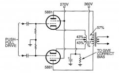
OK Walter, it isn't obvious on a detailed schematic, So here it is simplified, alto for 43% UL.
43% was simply a magic number put to use by Hafler & Keroes of Dynaco after they did a bit of research.
It was still reasonably easy to drive but the resulting Damping Factor before full loop NFB was good.
Quite a few people built 20% UL back in the day. UL could be anything, just find a OPT winder that would do it for you.
The winders will tell you every time the machine is stopped to bring out a tap or start another winding the price climbs.
Somewhere in Glass Audio / AudioXpress there is an article covering an amp with 57% UL, the builder has connected
the OPT primary windings opposite to what is normal, He used Menno's OPTs.
For several years Menno's high performance magnetic were built
here in the Toronto area. At 601 Magnetic Drive...................imagine that.
Stuffed into Crowhurst's version of his Twin Coupled Amplifier the UL is 50%.
Attachments
The McIntosh, the N. Crowhurst and the Circlotron are all the same framework, with different degrees of difficulty. The McIntosh requires a minimum of two bifilar primary windings, each with both polarities (for the usual push-pull versions, and Mc's were almost Class B, so push-pull only). The N. Crowhurst cheats a little, coupling the ends of two separate transformers' primaries, to get nearly as good coupling at the low impedances resulting from the framework. The Circlotron really cheats by making both windings the same piece of wire, but requires floating B+ supplies. All are gain-of-two output stages and need heroic driving voltages, commercially meaning bootstrapping the driver.
We probably shouldn't say that there's feedback to the screens - it'd be better to say that the screens are kept at the same signal voltage as the cathodes, making it full pentode operation. In the McIntosh and the N. Crowhurst, if the screens are instead connected to B+ (or some lesser zero-signal voltage) they operate at 50% partial triode ("UltraLinear").
All good fortune,
Chris
Reading Radiotron ( as reference) the UL is treated separately and in the paragraph of Mac nothing is written about UL operation.

So are different things
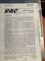
In attach a front page of MOV valve Application Report no.3 ( it is an original book)
Then the diagram where is possible to see that the 43% is not casual . In fact the Zout and distortion stay constant even you increase the % (from 40) of UL feedback, while the power goes down in the same shape with different Rl.
It is for KT88 tube but can be taken as general rules
And I take this informations as reference around the UL circuit.
Walter
So are different things
In attach a front page of MOV valve Application Report no.3 ( it is an original book)
Then the diagram where is possible to see that the 43% is not casual . In fact the Zout and distortion stay constant even you increase the % (from 40) of UL feedback, while the power goes down in the same shape with different Rl.
It is for KT88 tube but can be taken as general rules
And I take this informations as reference around the UL circuit.
Walter
Attachments

The McIntosh doesn't use partial triode ("UL") operation - it's full pentode - but it could be done if someone wanted to. Connecting screens to B+ (or a lower B+ for use with sweep valves, etc.) puts them at 50% of signal voltage relative to cathodes. This relation is the definition of Blumlein partial triode, which must be seen from the valve's perspective.
All good fortune,
Chris
All good fortune,
Chris
Last edited:
Pentode / Beam Power mode: The screen is tied to a steady / stiff voltage supply (If you insist on calling that Ultra Linear, then it is 0% UL).
Pentode / Beam Power Ultra Linear mode: The screen is tied to some percentage of the same tubes plate signal voltage (Often 20% to 80% of the plate signal voltage swing).
Triode Wired Mode of Pentode / Beam Power: The screen is tied directly to the plate of the same tube (or through a low resistance such as 100 Ohms),
(If you would like to call that Ultra Linear, then it is 100% UL).
If instead, you connect 2 triodes in totem pole configuration, then it is possible to make it work in Ultra Linear mode:
Example, just connect the top triode grid to the signal voltage of the same tube's plate. This is much more difficult to do, you have to use DC level shifting and a plate signal voltage divider, or other circuitry to make it work properly. Which raises the question: Why do it that way?
Just my opinions
Note: I never knew that cathode feedback from the plate is defined as Ultra Linear feedback to the screen.
What an interesting way to see it!
Last edited:
"UltraLinear" is a marketing ploy by some Americans to cash in on the original work of Alan Blumlien, who invented the idea of partial triode operation in the late 1930s. Not surprising, because he invented everything including differential amplifiers and stereo records, etc.
It's easiest to visualize the way 50/50 anode/cathode loading can be 50% partial triode with G2 at signal ground by making two drawings. In the first, we draw a sine wave at the grid, cathode, anode and G2. The first three will all be the same size (idealized for infinite OL gain) and the last will be a flat line. Cathode and anode will be of equal size and opposite polarity. If we re-draw these referencing the cathode, we have the cathode voltage as the flat line and anode as twice as big, and G2 as the same original size as the cathode or anode was originally, and in the same polarity as the anode. So, relative to the cathode (which is how valves think about things) G2 has 50% of anode voltage.
All good fortune,
Chris
- Home
- Amplifiers
- Tubes / Valves
- feedback in Shindo pushpull amp