Inventors:
There are lots of Original inventors. Don't forget any.
Flemming
DeForest
Bell Labs
Raytheon
(etc.)^ to the 10th power
And, Oskar Heil, who invented the FET (JFET) in the 1930s. That was before Bell Labs 1948 point contact transistor.
(there just was not any foundry that could build the JFET back then).
How about the original tunnel diode using a point contact Galena crystal. That was a really early one.
When it comes to 'sound amplification', the Chinese were first, they built multiple acoustic resonators at multiple frequencies.
Naming Conventions:
If I ground one of the grids of a dual triode long tailed pair balanced amplifier, should it now called a common cathode stage, and a grounded grid stage?
Like many De Forest did not invent the triode, he stumbled on to it, His PhD thesis covered conduction in flames.
He got a vacuum diode & his tech stuffed in another wire, on the other side. The result did some strange things.
When it worked as a detector of sorts it was very unstable, De Forest thought his thing had to contain a gas to operate.
The opposite was true & had to wait for a way of creating a better vacuum was found.
And Deforest was never able to properly explain the function of the result.
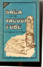
For a very good account of De Forest's lurching along to the triode from conduction in Bunsen Burner gas flames, get yourself a
copy of Gerald F Tyne's book Saga of the Vacuum Tube. The most important work came later in the labs of GE & Wesitinghouse
were better methods of pulling a good vacuum on an industrial scale & cathode materials that were efficient & dependable.
Another famous stumble was the XRay. But Roentgen was careful, He did more work before letting the World know of his discovery.
Roentgen was on the level, De Forest was not. De Forest had his lawyers chasing Edwin Armstrong, a for more knowledgeable inventor.
De Forest claimed the Superhet receiver & sued. A lawyers free for all was the result. David Sarnoff of RCA got in the middle,
Armstrong committed suicide. But his wife eventually prevailed.
And the lawyers always win.................................win or lose by the players.
At HP the corporate legal team spent a lot of time & resources to educate us in terms of legal matters that might effect the company
When you get big all kinds of people are nipping around the edges hoping for a big payout.
America is a litigious society,😈
He got a vacuum diode & his tech stuffed in another wire, on the other side. The result did some strange things.
When it worked as a detector of sorts it was very unstable, De Forest thought his thing had to contain a gas to operate.
The opposite was true & had to wait for a way of creating a better vacuum was found.
And Deforest was never able to properly explain the function of the result.
For a very good account of De Forest's lurching along to the triode from conduction in Bunsen Burner gas flames, get yourself a
copy of Gerald F Tyne's book Saga of the Vacuum Tube. The most important work came later in the labs of GE & Wesitinghouse
were better methods of pulling a good vacuum on an industrial scale & cathode materials that were efficient & dependable.
Another famous stumble was the XRay. But Roentgen was careful, He did more work before letting the World know of his discovery.
Roentgen was on the level, De Forest was not. De Forest had his lawyers chasing Edwin Armstrong, a for more knowledgeable inventor.
De Forest claimed the Superhet receiver & sued. A lawyers free for all was the result. David Sarnoff of RCA got in the middle,
Armstrong committed suicide. But his wife eventually prevailed.
And the lawyers always win.................................win or lose by the players.
At HP the corporate legal team spent a lot of time & resources to educate us in terms of legal matters that might effect the company
When you get big all kinds of people are nipping around the edges hoping for a big payout.
America is a litigious society,😈
Attachments

Osker's lump of material didn't stand a chance at ever working properly. At that time (1930s) crystals of high purity semiconductorAnd, Oskar Heil, who invented the FET (JFET) in the 1930s
materials where next to impossible to fabricate, One of the grad students in the lab where I worked, Bill Gravelle used zone refining
during his work on I think what was Indium. Bill escaped with his advanced degree from U of T Physics around 1959.
David Hafler of Dynaco. He somehow managed to copyright that for his version of the UL OPT. Kinda like Chrysler & 'Hemi'."UltraLinear" is a marketing ploy by some Americans
Oddly only for 43%. Everything else was still distributed load. His sidekick Herbert Keroes did the study that concluded 43% was best.
The key here, Hafler's company was in the OPT manufacturing business, And Herbert K disappeared. Doesn't even get his own
piece in Wikipedia.
https://worldradiohistory.com/Archive-All-Audio/Archive-Audio/50s/Audio-1951-Nov.pdf
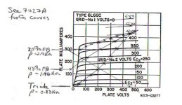
I was suspicious of that finding from the get go. For starters the output toobz used were 6L6s.
Any other tube such as an EL84 has a different mu g1 g2
I built me a graph of several UL percentages as well. The plate curves as a function of G2 voltage at G1 zero is a very
useful piece of information. When loading pentodes G2 curves are always worth a look.
Many people built PP partial triode at 20% as well as 43%. I also built SEP at 50%. Anything goes!
And quite a few stretched things by UL modification to the already unstable Williamson.
And the Mullard twins also got a lot of attention! 👍
Attachments
I don't mind their raw-data-free and suspiciously noiseless graphing like Fig.2, and I don't really mind their conflating overload recovery and low frequency stability with the subject of their puff piece. Thus it was and thus it ever shall be. What chaps my cheeks is their failure to mention the actual source of their "patent". Who, it turns out, died testing his contribution to airbourne radar during WW2. Gentlemen give proper credit, and they weren't gentlemen.
All good fortune,
Chris
All good fortune,
Chris
Thanks to our friends who wrote good information about the and the history of the amplifier. simens used 3 feedback line in el34 pushpull .The character of the sound of an amp and its working stability depend on the feedbacks.
.gif") .
.
Hi
I found the article by Crowhurst and I am trying to read and (if possible) to understand ( with my poor english).
But, reading the description of twin coupled circuit, nothing is referrd to UL.
But I will read again and again!!
🙂
Walter
I found the article by Crowhurst and I am trying to read and (if possible) to understand ( with my poor english).
But, reading the description of twin coupled circuit, nothing is referrd to UL.
But I will read again and again!!
🙂
Walter
Post 26 : which Siemens model could this be ?
FB taken from the output tube plates was quite common in german pp studio amps.
FB taken from the output tube plates was quite common in german pp studio amps.
The S&H cct with the two kinds of NFB path appears in many forms in the later RCA Receiving Tube Manuals.
For example cct # 29-11 in RC-30 which adds yet another level of NFB in this cct, that being Schade.
Must have been rather common & well known. 👍
For example cct # 29-11 in RC-30 which adds yet another level of NFB in this cct, that being Schade.
Must have been rather common & well known. 👍
The S&H amp also reminds of a Williamson where the original builder has reconnected the output KT66 or 807s
from triode to pentode, than got the overall circuit gain back to the original & restored stability using some internal NFB. Maybe.😀
from triode to pentode, than got the overall circuit gain back to the original & restored stability using some internal NFB. Maybe.😀
The McIntosh amplifier & original circuit does not have a UL connexion at all.in the paragraph of Mac nothing is written about UL operation.
I added it to my version of Crowhurst's Twin Coupled Amp. It is one of the several
alternations mentioned in Crowhursts article, ' Triodes vs Pentodes'.
The amp I built is/was for experimental purposes for which it served well.
And still does. Anyone wants an improved copy of the published article with added information,
just PM me.👍
SIEMENS EL34 AMP SV410 / 1 ....Post 26 : which Siemens model could this be ?
FB taken from the output tube plates was quite common in german pp studio amps.
I think it is an internal positive feedback circuit thamed by an external negative feedback secondary-to-input to avoid oscillations.
If the positive feedback level is too large, then . . .
Perhaps it is a US Navy Klaxon Alarm . . .
Arrruuuuga
Dive, Dive, Dive
Perhaps it is a US Navy Klaxon Alarm . . .
Arrruuuuga
Dive, Dive, Dive
Agreed! Completely. And I'd bet a dime those 5R4GY rectifiers make a huge difference as this thing performs in Tibet at 12000 feet! 😀The schematic in post #33 is drawn incorrectly.
😀
For the schematic in Post # 33:
Two sets of RC coupling between the stages, AKA ~ Williamson (those two RC couplings are inside of the global negative feedback loop, and the 3rd low frequency pole is the output transformer).
And positive feedback from the output tube plates, through a 0.1uF cap to 100k series resistor, to the low impedance driver cathodes. Estimated frequency where the relative positive feedback is about -3dB at 15.9 Hz, less positive feedback at lower frequencies.
The fixed bias parallel 6550 tube pairs have common 56k g1 return resistor to the bias, plus 10k grid stoppers.
I calculate that as effectively 56k x 2 + 10k = 122k Ohms per g1 grid.
6550 spec for fixed bias is 50k Maximum.
That circuit is asking for OUCH, broken, run-away current on most 6550 tubes.
And, there is no individual bias for each output tube pair (use extremely well matched pairs, or one is certain to run-away).
Tibet atmosphere is almost as rare as the vacuum in very early tubes. Ha Ha
Last edited:
- Home
- Amplifiers
- Tubes / Valves
- feedback in Shindo pushpull amp