G.Kleinschmidt said:I guess that would depend on what you mean by "very low".
Your run-of-the-mill SET power amp may be pushing 10% THD or more a its rated power output, but you could conceivably parallel up some big power tubes and run them with high plate impedance to get the THD down (ie, lots of dissipation for very little output). Ideally, you would want tubes intended for not-too-high voltage operation at high currents, as there is a practical limitation to how high you can go with the impedance presented to the plate before the design of the impedance matching transformer becomes a headache.
Thanks Glen.
Honest mistake, I took the phrase "generate copious amounts THD and IMD (such as the open-loop SET brigade)" as dismissal of open loop SE in the context of a thread about using GNFB to reduce distortion. Go figure.
Is global feedback limited to high power amplifiers? Why not pre-amps? Or a ngnfb two-stage SE tube headphone amp that swings 4 vp-p into 60 ohms (110db with AKG 701s) at ~0.02% very predominantly second? Normal listening levels well under 0.01%. No 2nd order cancellation.
Is global feedback limited to high power amplifiers? Why not pre-amps? Or a ngnfb two-stage SE tube headphone amp that swings 4 vp-p into 60 ohms (110db with AKG 701s) at ~0.02% very predominantly second? Normal listening levels well under 0.01%. No 2nd order cancellation.
rdf said:Honest mistake, I took the phrase "generate copious amounts THD and IMD (such as the open-loop SET brigade)" as dismissal of open loop SE in the context of a thread about using GNFB to reduce distortion. Go figure.
The title of this thread is:
“Feedback in amplifier is ultimately the driver of sound quality ?”
I used a SET power amplifier as an example of a type of amplifier where GNFB is often not used because it (in part) diminishes a sonic characteristic for which some prefer it – that is high levels of low order distortion.
rdf said:Is global feedback limited to high power amplifiers?
No. Is that under debate?
Hi Andy
Real low distortion no-GFB tube designs are often push-pull and rely on the use of the most linear gain cells one can find... only a few tubes qualify (most of them from the ages before GFB was invented).
You might take a look at Lynn Olson's site (also a DIYA member):
http://nutshellhifi.com
and especially, for an example of a low distortion no-GFB amp:
http://nutshellhifi.com/triode2.html
a qickstart to some of his articles:
http://nutshellhifi.com/library/index.html
He is a very serious guy (a former Tektronix employee), no signs of technical ignorance of any sorts, and he has serious friends/partners (e.g. Gary Pimm, also a "Tekkie")
- Klaus
With SET design this is quite hard to obtain, because they cannot make use of even order cancelling, that is, the lower intrinsic 3rd harmonic is not of much benefit, in total. Also, the output tranny is always somewhat compromised because of the DC bias current (there are other output stage designs, avoiding DC in the xformer, though).andy_c said:So are there actually any SET power amps having no GNFB, and that have very low distortion? This is a serious question - I'm completely ignorant of the vacuum tube world.
Real low distortion no-GFB tube designs are often push-pull and rely on the use of the most linear gain cells one can find... only a few tubes qualify (most of them from the ages before GFB was invented).
You might take a look at Lynn Olson's site (also a DIYA member):
http://nutshellhifi.com
and especially, for an example of a low distortion no-GFB amp:
http://nutshellhifi.com/triode2.html
a qickstart to some of his articles:
http://nutshellhifi.com/library/index.html
He is a very serious guy (a former Tektronix employee), no signs of technical ignorance of any sorts, and he has serious friends/partners (e.g. Gary Pimm, also a "Tekkie")
- Klaus
Thanks Klaus. Sorry for dragging this off-topic. I guess I've generically thought of "SETs" as being synonymous with "SET power amps", when this is not so.
Andy wrote:
Andy, I'm not sure what you are saying about NFB adding new spectra.
I believe I could have used any non-linear amplifer equation you like and got a similar result.
I'm not familiar with Baxandall's paper...have you got a copy you could email to me?
Would you help me out with your reference to Bob's post which I have now read. I'm not sure what you are concluding from it. IMO Bob's simulation is too simplistic to draw any conclusions about additional spectral content. Bob writes "Here appears to be a very important case where the application of NFB does not introduce or enhance any distortion components." but he neglects to justify why he considers it to be an important case. It would be erroneous to conclude it is other than a special case.
Brian
Well, you've chosen the operating point to be Vout=Vin=0. At this operating point, the derivative of Vout with respect to Vin of the open-loop device is zero. So small-signal-wise, its gain is zero. That's why I called it a frequency multiplier. But it's not the name that's important. It's the behavior, and whether that behavior is representative of real-world situations.
I'm not sure if y'all were aware of the posts on this subject that went on in the Bob Cordell negative feedback thread. It started with a discussion of Baxandall's paper in Wireless World, where, for a fixed output voltage amplitude, he took the open-loop amplifier to be a square law device (a JFET) and plotted the amplitude of the harmonic distortion components vs. the amount of feedback.
Bob got the idea of duplicating his results with SPICE, and was able to do so, both for Baxandall's JFET and BJT analysis. But then he also posed an interesting question. What happens with crossover distortion of a BJT class AB output stage? Do some values of feedback increase higher-order harmonics in the same way as what occurs with a square law device such as a JFET? It turns out that it doesn't. It reduces them pretty uniformly. So while the JFET case shows some interesting behavior with varying feedback, it's incorrect to generalize the results of that case. Bob's post is number 1278 on this page
These results cause me to conclude that the so-called "SPLIF" concept is without merit.
Andy, I'm not sure what you are saying about NFB adding new spectra.
I believe I could have used any non-linear amplifer equation you like and got a similar result.
I'm not familiar with Baxandall's paper...have you got a copy you could email to me?
Would you help me out with your reference to Bob's post which I have now read. I'm not sure what you are concluding from it. IMO Bob's simulation is too simplistic to draw any conclusions about additional spectral content. Bob writes "Here appears to be a very important case where the application of NFB does not introduce or enhance any distortion components." but he neglects to justify why he considers it to be an important case. It would be erroneous to conclude it is other than a special case.
Brian
traderbam said:I believe I could have used any non-linear amplifer equation you like and got a similar result.
I thought that too, until i used an exp() as transfer function. Try it!
Mike
traderbam said:Andy, I'm not sure what you are saying about NFB adding new spectra.
Ah, this is a bit confusing because the thread I referred to was all about trying to first duplicate, then extend the results of Baxandall's article. If you haven't read the Baxandall article, then the context is lost.
I believe I could have used any non-linear amplifer equation you like and got a similar result.
I'm not familiar with Baxandall's paper...have you got a copy you could email to me?
I'll send you a copy, but I'll also try to summarize it briefly here.
Baxandall did a study of the effect of feedback (approximately independent of frequency) on distortion components of various orders for a simple JFET and BJT amplifier. He started with a JFET with the signal level cranked up so that it had about 1 percent distortion without feedback, consisting almost entirely of second harmonic. He then increased the feedback and plotted the relative levels of harmonics of order up to about six I think. You could see that feedback caused an increase in higher-order distortion starting out, then as the feedback became large, these higher-order components would decrease in amplitude again. This result has sometimes been generalized to assert, in effect, that small amounts of feedback always increase distortion, and only begin to decrease it again when the feedback is larger than some critical amount (dependent on the harmonic order). It has also been asserted, based on Baxandall's JFET results, that feedback always increases higher-order harmonics. But are those assertions correct in all cases? That leads to the next question...
Would you help me out with your reference to Bob's post which I have now read. I'm not sure what you are concluding from it. IMO Bob's simulation is too simplistic to draw any conclusions about additional spectral content.
Bob's simulation was meant to do the same thing that Baxandall did, except using a class AB output stage instead of a JFET. Bob's simulation was simplistic because Baxandall's was. Baxandall's study was simplistic in an attempt to bring key concepts to light.
Have you ever simulated a DC sweep of the output of a class AB BJT output stage and tried to fit the results to a polynomial using least squares? If you have, you'll realize that to get the fine wiggles near the origin, combined with the gradual bend for larger input and output, you'll need a full-on infinite Taylor series. Because of the trig power relations, this implies that for a sine wave input, the output will contain all harmonics. Given this situation, the concern of "adding new harmonics" is moot - they're already all there. So then what happens when feedback is applied around this circuit? It turns out that even for small amounts of feedback, all orders of distortion that were examined were reduced. This appears to be in conflict with Baxandall's results, but it is really only in conflict with some incorrect generalizations of them. So attempting to generalize Baxandall's JFET results can lead to errors.
Bob writes "Here appears to be a very important case where the application of NFB does not introduce or enhance any distortion components." but he neglects to justify why he considers it to be an important case. It would be erroneous to conclude it is other than a special case.
If you are not concerned with the effect of feedback on the distortion introduced by class AB output stages, then it's not important. If you are, it is important. About special cases, that's exactly right. It brings up the issue that the effect of feedback on distortion needs to be treated on a case-by-case basis. One cannot safely generalize Baxandall's JFET results as some, including Cheever, have done. Bob's example serves as a counterexample to that.
Cherry shows the same math in his jaes paper
Estimates of Nonlinear Distortion in Feedback Amplifiers
Volume 48 Number 4 pp. 299-313; April 2000
Estimates of Nonlinear Distortion in Feedback Amplifiers
Volume 48 Number 4 pp. 299-313; April 2000
traderbam said:Mike, I have tried it.
Could you elaborate on the equation/simulation you used?
Brian
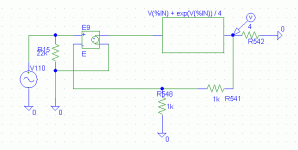
Brian, see attachment for spice circuit i used... I took the expression evaluator for different functions.
I did some more research. Using the equation "Cg = K / (1 + K/Og)" for feedback loop (Cg = closed loop, K = feedback divider, Og = open loop) with unity gain, you end up with a gain function y = 1 / (1 + x), where x is 1 / open loop gain.
Looking at the taylor series for y = 1 / (1 - x) Wiki You see that this functions is simply a sum of all polynomials.
This should mean, that a closed loop transfer is always rich of harmonics, if x is not constant. If x is constant, the result is also constant = distortion free.
I think, that if open loop distortion is reasonably low and feedback not too low, this effect is negligible.
Mike
Attachments
Mike, if you or anybody else would like a copy of those Baxandall articles, just shoot me an email and I'll send them to you.
Ok, thanks for the explanations Andy and Mike and for the Baxandall articles, Andy. That's very helpful. It looks rather involved so I'll study it carefully and I'll consider your model, Mike, and get back to both of you as soon as.
Brian
Brian
andy_c said:
Ah, this is a bit confusing because the thread I referred to was all about trying to first duplicate, then extend the results of Baxandall's article. If you haven't read the Baxandall article, then the context is lost.
I'll send you a copy, but I'll also try to summarize it briefly here.
Baxandall did a study of the effect of feedback (approximately independent of frequency) on distortion components of various orders for a simple JFET and BJT amplifier. He started with a JFET with the signal level cranked up so that it had about 1 percent distortion without feedback, consisting almost entirely of second harmonic. He then increased the feedback and plotted the relative levels of harmonics of order up to about six I think. You could see that feedback caused an increase in higher-order distortion starting out, then as the feedback became large, these higher-order components would decrease in amplitude again. This result has sometimes been generalized to assert, in effect, that small amounts of feedback always increase distortion, and only begin to decrease it again when the feedback is larger than some critical amount (dependent on the harmonic order). It has also been asserted, based on Baxandall's JFET results, that feedback always increases higher-order harmonics. But are those assertions correct in all cases? That leads to the next question...
Bob's simulation was meant to do the same thing that Baxandall did, except using a class AB output stage instead of a JFET. Bob's simulation was simplistic because Baxandall's was. Baxandall's study was simplistic in an attempt to bring key concepts to light.
Have you ever simulated a DC sweep of the output of a class AB BJT output stage and tried to fit the results to a polynomial using least squares? If you have, you'll realize that to get the fine wiggles near the origin, combined with the gradual bend for larger input and output, you'll need a full-on infinite Taylor series. Because of the trig power relations, this implies that for a sine wave input, the output will contain all harmonics. Given this situation, the concern of "adding new harmonics" is moot - they're already all there. So then what happens when feedback is applied around this circuit? It turns out that even for small amounts of feedback, all orders of distortion that were examined were reduced. This appears to be in conflict with Baxandall's results, but it is really only in conflict with some incorrect generalizations of them. So attempting to generalize Baxandall's JFET results can lead to errors.
If you are not concerned with the effect of feedback on the distortion introduced by class AB output stages, then it's not important. If you are, it is important. About special cases, that's exactly right. It brings up the issue that the effect of feedback on distortion needs to be treated on a case-by-case basis. One cannot safely generalize Baxandall's JFET results as some, including Cheever, have done. Bob's example serves as a counterexample to that.
Well stated, Andy.
Also, one of the most interesting things shown in the permanent NFB thread was that even simple emitter degeneration has the effect of initially increasing some of the higher order harmonics until the amount of NFB goes beyond 10 dB or so.
Cheers,
Bob
Bob Cordell said:Also, one of the most interesting things shown in the permanent NFB thread was that even simple emitter degeneration has the effect of initially increasing some of the higher order harmonics until the amount of NFB goes beyond 10 dB or so.
Yes, that was a very interesting thread. I learned a lot from it.
Another thing that was discovered was the effect of using emitter degeneration vs. global feedback. For the emitter degeneration case, if you define the loop gain as gm*RE, then the distortion components end up being the same as if you have frequency-independent global feedback with the same loop gain value.
One perhaps dimwitted question, in these simulations is the feedback return distorted to model the non-ideal transfer function from the feedback input to device output?
rdf said:One perhaps dimwitted question, in these simulations is the feedback return distorted to model the non-ideal transfer function from the feedback input to device output?
This gets a bit confusing because of the different configurations that were simulated. There was the single JFET case, the single BJT case, and the BJT class AB output stage case. Further confusing things is the fact the the signal sampled could be a voltage or current, and the signal fed back could also be a voltage or current.
For the case of the single JFET (BJT), the signal sampled was the source (emitter) current, and the signal fed back is the source (emitter) voltage. Looking at the classical feedback block diagram, the output of the difference block (the error signal, = input minus sampled and scaled output) is Vgs in the JFET case and Vbe in the BJT case. So all the nonlinearity is lumped into the open-loop block. It's a square law function in the JFET case and an exponential function in the BJT case.
In the case of the BJT class AB output stage, there is no differential input, so the difference signal was formed by an ideal difference network. In reality, this would be a diff amp having its own distortion, but trying to model this would only add more variables and confuse things. The idea wasn't so much to get an accurate estimation of a real amplifier, but to break the problem into pieces, looking at only the piece of the puzzle corresponding to the distortion of the output stage.
I hope I haven't confused things further.
I was thinking more the general case. For example, is the circuit below equivalent to MikeB's (ignoring for the moment the exact transfer function at the feedback return node might not be the same as the positive input)? The two transfer boxes and summing nodes represent of course components of a single device. If not, which is more representative of the general case?
Attachments
Oh, I think I see what you're getting at.
Your diagram is equivalent to Mike's but if the two nonlinear blocks are different, then that's a more general case. In that more general case, the output of the nonlinear circuit would be a function of, say, V1 and V2, but it could not be expressed as purely a function of the difference mode voltage V1-V2.
Another way to think of that is the nonlinear circuit's output being a function of both difference-mode and common-mode input effects. The sims that were done in the Cordell negative feedback thread with the BJT and JFET would take into account common-mode effects via the Early voltage in the BJT case and the non-zero output conductance that's a function of Vgs in the JFET case. This would be handled internally by SPICE. I think the models that ware picked were just typical devices like the 2N5551, with no attempt made to manipulate or determine the effects of the Early voltage. In retrospect, I guess the Early voltage should have been removed from the models so the default value of infinity would be used. That would put the results closer to Baxandall's theoretical predictions that neglected the Early effect.
The idea was to isolate and simplify as Baxandall did. Since those sims were intimately connected to Baxandall's approach and results, it becomes confusing to discuss them outside that context. So the response to questions such as "Why was it done in such-and-such a way" becomes, "Because that's how Baxandall did it. The purpose and scope of the problem were to first duplicate his results, then extend them a bit". If you're not familiar with what Baxandall did, the article is a very worthwhile read. It would also make the discussion easier by putting the work of the Cordell feedback thread into context.
- Status
- Not open for further replies.
- Home
- Amplifiers
- Solid State
- Feedback in amplifier is ultimately the driver of sound quality ?