To compare a conventional amp at 1W in 8R with an Aleph 3 at 37,5W in 4R is same kind of telling the truth as Mr. Bush does. You blame yourself.
till said:To compare a conventional amp at 1W in 8R with an Aleph 3 at 37,5W in 4R is same kind of telling the truth as Mr. Bush does. You blame yourself.
I am absolutely not interested in the results of that commercial amp at 1W, those results are horrible. But you can have a look at my website, there are 2 push-pull class A designs + THD measurements. They are of the same power rate as A3.
Talking about commercial design, you may have a look at distortion of Classé CAM350, for example.
Re: SPL!!!!!
That's another thing. JA's often all over the road with regard to what power levels he measures distortion.
se
pjacobi said:You must compare plots of equal output.
The first graph are 134W, the last one 1W. Big wonder, there's a difference.
(I would prefer to see graphs for 10W and 0.1W, BTW)
That's another thing. JA's often all over the road with regard to what power levels he measures distortion.
se
AKSA said:And now the $64K question:
1. ARE WE MEASURING THE WRONG THING?
2. IS HARMONIC SPECTRUM RELEVANT AT THESE LEVELS?
3. ARE WE IMAGINING DIFFERENCES WHERE NONE EXIST?
4. ARE SONIC DIFFERENCES ATTRIBUTED TO SOMETHING COMPLETELY DIFFERENT WE HAVEN'T THOUGHT OF YET?
Good questions.
Though I don't know if they can be answered adequately. Given that different people can have wildly different responses to the exact same presentation under the exact same circumstances, I don't know that we'll ever be able to come up with any meaningful answers. At least not on any sort of broad scale.
By that I mean even if you can put your finger on something which indeed does result in some audible difference, you're likely to have some number of people who feel that said difference sounds good while some other number of people will feel that it sounds bad.
Personally I tend not to care too much about measurements and just go with what sounds best to me and not worry about other people's axioms such as "negative feedback is bad."
In true Australian, 'Are we just a bunch of tossers?'
Perhaps.
But as long as we're having fun and enjoying ourselves, who cares? 🙂
se
i might as well toss this in...
I think this is a more or less “apples-to-apples” comparison of ce, ef, and cfp performance – the devices and loads are due to my interest in headphone amplifiers; the levels are matched for similar load v and i with identical output Qs
The darlington trace should be essentially indistinguishable from the single ef (which I didn’t do) and I believe it can be seen that the distortion spectrum follows the oft criticized negative feedback distortion characteristic of reduced low frequency distortion with the higher order distortion components eventually exceeding the no feedback ce distortion – just think ef = dar in most of the discussion
The cfp case however shows that with enough feedback the distortion crossover can be pushed way below the noise floor – in this sim it is obscured by the resolution of spice calculations and while model inaccuracy certainly renders the absolute values of the lower distortion numbers irrelevant, the relative distortion with varying feedback around identical devices should serve to illustrate the point that just because a little feedback may be “bad” (the “evil” 5th, and 7th harmonics just = in ce vs dar and the 1st higher dar harmonic is @ –120 dB), it doesn’t mean a lot of feedback (in the cfp) can’t be very good
a quick shortcut for how much more feedback does the cfp have vs the ef:
how much more current flows into the load/Q3_emitter junction due to Q1?
ic_Q1 = h_fe * ib_Q1, ib_Q1 = ic_Q3; therefore the cfp has h_fe (of Q1) more gain than Q3 would have as a single Q ef
so why isn’t the distortion of the cfp -46 dB ( h_fe of Q1 is ~210 ) vs the darlington trace?
Because a major distortion source is the distortion of v_be (of Q3 in the cfp, largely Q2 in the darlington) and it is “outside” of the loop and is only indirectly reduced in the cfp by the gain of Q1 reducing the current swing in Q3
Attachments
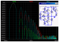
PMA said:This is funny, as all of those much loved zero feedbacks, simple the bests etc. have not only 2nd a 3rd harmonics, but the full row of them like mountains and ridges. Look at Ayre-V3, measurement by Stereophile, typical example:
Hello Pavel,
For a guy that claims to design amplifiers, you seem to be missing a few points regarding distortion. The graph you posted for the distortion of the Ayre V-3 shows a strong fundamental with a series of declining odd harmonics, starting with the 3rd harmonic at about 0.3%:

Now if you know anything about the Fourier series of common repetitive waveforms, you will recognize this as (drum roll, please) a combination of a large sine wave and a smaller square wave of the same frequency. The reason is simple. Please look at the graph of the same review of THD versus power level:
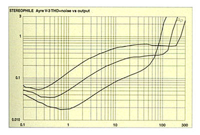
One can easily see that there is a "knee" at about 120 watts into 4 ohms. Above that knee, the distortion climbs because the amp is entering clipping. Since spectrum you posted was taken at 134 watts, it is no surprise whatsoever that there will be a series of odd harmonics that decrease in level as the frequency increases. That is what clipping looks like when measured on a spectrum analyzer! To make fun of an amplifier because it has high distortion when it is clipping make no sense to me....
Now in my experience, lower distortion is better than higher distortion if all other factors are equal. I think we are in agreement here. Please refer to a more recent design of mine where I have achieved better measured performance, without resorting to the use of feedback:
Where we differ in our opinions is that, in my experience, adding feedback to a circuit to reduce the steady-state distortion measured into a resistive load on the test bench takes one step forward and two steps backwards from the standpoint of actually listening to the equipment. You disagree, based on your experiences. That is fine. I have no argument with that. You are free to build your amplifiers the way you like, and I will continue to build mine the way I like.
Best regards,
Charles Hansen
Charlie's measurements are similar to the open-loop amps that I have made. And I have made several.
The people who bought them are happy. Their checks cleared, so I am too.
End of discussion, AFAIAC.
Jocko
The people who bought them are happy. Their checks cleared, so I am too.
End of discussion, AFAIAC.
Jocko
What about TIM in all these THD focused discusions lately.......anybody......any figures.......Czech duo.........? 🙄
Cheers! 😉
Cheers! 😉
Charles - Thanks for the kind words a few days back. I stay out of these discussions as a rule, after all some of you folks are customers.  I have a couple of Hafler DH220's collecting dust, do you think I could rework them into the form of that circuit you posted of your early power amp? I mean could I use the output devices and power supply and rework the rest to a creditable OL amp?
Jocko - Here's your chance. I saw the original run in '67, BCNU
http://cgi.ebay.com/ebaymotors/ws/eBayISAPI.dll?ViewItem&category=6312&item=2463316628
As a side note, the level of bad feelings and acrimony in these threads is a turn off, but I'm sure you all know this already.
I have a couple of Hafler DH220's collecting dust, do you think I could rework them into the form of that circuit you posted of your early power amp? I mean could I use the output devices and power supply and rework the rest to a creditable OL amp? Jocko - Here's your chance. I saw the original run in '67, BCNU
http://cgi.ebay.com/ebaymotors/ws/eBayISAPI.dll?ViewItem&category=6312&item=2463316628
As a side note, the level of bad feelings and acrimony in these threads is a turn off, but I'm sure you all know this already.
Re: i might as well toss this in...
Thanks for the comparative analysis, jcx!
My particular preference for the CFP over the Darlington is limited to its use as a single-ended follower with an N-channel JFET up front and a PNP bipolar for the output.
Have you done any comparative analysis of this combination versus the all-bipolar CFP?
I've been somewhat curious as to what it's basic behavior would be seeing as the two devices are complimentary in terms of their polarity and in their own local loop, yet one is a square law device while the other is exponential.
se
jcx said:I think this is a more or less “apples-to-apples” comparison of ce, ef, and cfp performance – the devices and loads are due to my interest in headphone amplifiers; the levels are matched for similar load v and i with identical output Qs
Thanks for the comparative analysis, jcx!
My particular preference for the CFP over the Darlington is limited to its use as a single-ended follower with an N-channel JFET up front and a PNP bipolar for the output.
Have you done any comparative analysis of this combination versus the all-bipolar CFP?
I've been somewhat curious as to what it's basic behavior would be seeing as the two devices are complimentary in terms of their polarity and in their own local loop, yet one is a square law device while the other is exponential.
se
Re: i might as well toss this in...
By the way, the issue of how much feedback was with respect to the CFP versus Darlington, not CFP versus a single device emitter follower.
se
jcx said:a quick shortcut for how much more feedback does the cfp have vs the ef:
how much more current flows into the load/Q3_emitter junction due to Q1?
ic_Q1 = h_fe * ib_Q1, ib_Q1 = ic_Q3; therefore the cfp has h_fe (of Q1) more gain than Q3 would have as a single Q ef
By the way, the issue of how much feedback was with respect to the CFP versus Darlington, not CFP versus a single device emitter follower.
se
Charles,
the 3rd harmonic at the image posted is -50dB. As you know, this corresponds to approx. 0.3% of THD at 3rd harm, as 20 log (0.003) = -50.45. Now look back at the THD vs. power response for 4 Ohm load. 0.3% THD can be seen between 20W and 120W of output power, this is nothing about clipping.
Best regards,
Pavel
dummy speaker load etc.
The distortion measured into the dummy loudspeaker load is always worse than the one measured into pure resistive load - everybody knows, just a trivial elementary school example. Unfortunately the case of real loudspeaker box is even worse than the dummy loudspeaker load, as there are more speakers and the crossover circuit. The lower damping factor, the worse results (Pass Zen is the perfect example). Active crossover makes the situation considerably better.
Or - probably this is a so called pleasant "harmonic fullness"? 😉
I do not want to be pesimistic. There are excellent circuit designers, and I would like to mention Hawksford, Cordell, Blomley, Candy and Russell.
I am confused as to what you folks want or expect.
First, Charles Hansen pointed out that the spectrum that referred to his amplifier, was when his amp was approaching clipping. This is NOT a good place to get an impression about the audio quality of an amp.
In my JC-1, the same measurement was made at over 600W into 4 ohms. Is this listening level?😕 No, but many good amps take extraordinary measurement equipment and techniques to get the higher order harmonics measurable on traditional test equipment. For example, with 20W into 4 ohms into a JC-1, I could measure a difference in the 5th harmonic between the high and low bias. About -115dB with low bias, better than -120dB at high bias. 'Stereophile' did not note this difference in their review. Still, I think that a 20W measurement is MUCH more important than at powers greater than 100W.
Also folks, please consider the nature of the graphs presented. They are in dB! IF you looked at the graph on a linear scale, the higher order distortions would not be seen, except as a smudge at the bottom of the graph. This can distort the perception of the actual linearity of the design being tested.
john curl said:Also folks, please consider the nature of the graphs presented. They are in dB! IF you looked at the graph on a linear scale, the higher order distortions would not be seen, except as a smudge at the bottom of the graph. This can distort the perception of the actual linearity of the design being tested.
Your cable distortion measurements were in dB too. Were you trying to distort the perception of the actual linearity of the cables? If a decibel scale is appropriate for cable distortion measurements, why is it inappropriate for amplifier distortion measurements?
There's a very good reason why we use a decibel scale rather than a linear scale when it comes to things audio. I'm sure you have a book in your technical library that will tell you what that reason is.
se
There's a very good reason why we use a decibel scale rather than a linear scale when it comes to things audio. I'm sure you have a book in your technical library that will tell you what that reason is.
Actually, John's point is a really good one. Interpreting graphs is a skill not universally shared (sad, but true). And I'm inclined to believe that the levels here (as well as those seen in John's cable measurements, whatever their source) are below the threshold of audibility. The important stuff for amplifier audibility (IMO) is not covered in simple measurements like this as long as the distortion is reasonably low.
PMA:
What shall I say after I have done what? Your mesage is most unclear to me.
It doesn't help either, that I see nothing in common between my post and Till's.
Regards,
Peter Jacobi
PMA said:Till and Peter,
say it after you have ever tried that.
What shall I say after I have done what? Your mesage is most unclear to me.
It doesn't help either, that I see nothing in common between my post and Till's.
Regards,
Peter Jacobi
- Status
- Not open for further replies.
- Home
- Amplifiers
- Solid State
- Feedback artifacts, cars and semantics