SY said:Actually, John's point is a really good one. Interpreting graphs is a skill not universally shared (sad, but true). And I'm inclined to believe that the levels here (as well as those seen in John's cable measurements, whatever their source) are below the threshold of audibility.
But the issue of audibility is rather irrespective of how the levels are graphed.
The fact remains that there is a very good reason why we express them in decibels rather than absolute units.
The important stuff for amplifier audibility (IMO) is not covered in simple measurements like this as long as the distortion is reasonably low.
That's a whole other issue in my opinion.
se
Actually, I made 2 points about measuring amps. First, you have to measure the amp at its 'working level' to get an idea of what it will sound like from distortion measurements, and even that might not tell you enough.
This is not normally done by 'Stereophile'.
Secondly, it is important to NOTE that harmonic distortion levels are most often expressed in dB. This brings up the lower levels to almost match the higher levels. This is good for measurement, but bad for complete understanding.
Thirdly, I might also recommend a formula for 'weighting' the harmonics. This changes things again:
harmonic multiplier is equal to (n-1)!/2 This gives: 2nd=1/2, 3rd=1, 4th=3, 5th=12, etc. This implies that higher order harmonics are VERY bad for audio quality.
Steve Eddy said:
But the issue of audibility is rather irrespective of how the levels are graphed.
The fact remains that there is a very good reason why we express them in decibels rather than absolute units.
Hm, there are good reasons for it. I guess one could also argue
for other types of graphs being relevant. One obvious reason
is that the log scale makes it possible to read off even very small
figures (that is usually why log scales are used anywhere). It also
seems obvious since we translate duobling, tripling, etc. into
additive pehnomenae. however, there are also other issues to
consider. While a doubling of voltage/current is 6dB and a doubling
of power is 3dB, this seems not quite correspond to how our
hearing perceives it. I don't remember any references off the top
of my head, but I seem to rember it takes about 10dB for the ear
to perceive a doubling of the sound level, although I think this
also depends on what SPL we start at. How this relates to
preceiving the relative amplitude of harmonics is probably even
more obscure.
john curl said:Secondly, it is important to NOTE that harmonic distortion levels are most often expressed in dB. This brings up the lower levels to almost match the higher levels. This is good for measurement, but bad for complete understanding.
Levels aren't expressed in dB simply because it's "good for measurement." It's done because it's the most germane with regard to how our sense of hearing operates.
So if the "understanding" you speak of has anything to do with our sense of hearing, then it's best to use decibels.
If on the other hand all you want to do is present customers with a bunch of graphs that simply LOOK impressive, use a linear scale.
Thirdly, I might also recommend a formula for 'weighting' the harmonics. This changes things again:
harmonic multiplier is equal to (n-1)!/2 This gives: 2nd=1/2, 3rd=1, 4th=3, 5th=12, etc. This implies that higher order harmonics are VERY bad for audio quality.
Ok.
But for them to be "VERY bad for audio quality" they must also be audible unless you're speaking purely in some abstract philosophical sense.
If you've got high order harmonics present, but they're 120dB down from the fundamental, are they just as "bad" as if they were much higher? If not, at what point do you stop losing sleep over them?
se
Christer, I think you are correct. DB is usually used to keep everything on the chart. My equipment can measure either way, so I might look at it more closely. The weighting factor could be converted to decibels, and then added to the graph. It might make interesting comparisons.
Actually, I don't take much stock in absolute harmonic amplitude. We know that global negative feedback can reduce distortion to virtually unmeasurable levels, but we seem to still hear the amp's 'character'. In fact, I have designed two amps that measure almost exactly the same, except for a power increase of about 2 at most , and these two amps sound significatly different from each other. Go figure.
Actually, I don't take much stock in absolute harmonic amplitude. We know that global negative feedback can reduce distortion to virtually unmeasurable levels, but we seem to still hear the amp's 'character'. In fact, I have designed two amps that measure almost exactly the same, except for a power increase of about 2 at most , and these two amps sound significatly different from each other. Go figure.
john curl said:Christer, I think you are correct. DB is usually used to keep everything on the chart.
Come on, John. Surely you must have at least a basic text on acoustics and human hearing there.
se
I would never have imagined that those retired designers would use that ridiculous arguments (linear scale etc.) to excuse poor results of their designs.
Well folks, the dB scale is used throughout the engineering community. It is used in RF, instrumentation, and audio. It can confuse things for engineers on some occasions. For example, on a data sheet, transistor Beta change with current is usually expressed in dB. This is a problem, BECAUSE it makes the Beta curve appear TOO FLAT.
By the way, PMA, have you seen MY power amplifier curves in 'Stereophile'? Check it out in FEB 2003, or you might look at my earlier design in JAN 2000. I don't have to apologize for ANYTHING!
I use global negative feedback, so my distortion curves are going to look pretty good. Charles does not, so his distortion curves are going to have a higher level of distortion. However, measuring CLIPPING is dumb. Even measurements over 50W for fine detail are suspect.
John,
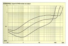
but it was not about clipping. Distortion vs. power plot shows the 0.3% THD+N for power from 20W to some 110W (middle curve, 4 Ohm load). 0.3% THD means -50dB which corresponds to the spectrum shown.
Regards,
Pavel
BTW - log scale is used in audio because of the nature of human ear perception.
but it was not about clipping. Distortion vs. power plot shows the 0.3% THD+N for power from 20W to some 110W (middle curve, 4 Ohm load). 0.3% THD means -50dB which corresponds to the spectrum shown.
Regards,
Pavel
BTW - log scale is used in audio because of the nature of human ear perception.
Attachments
john curl said:
By the way, PMA, have you seen MY power amplifier curves in 'Stereophile'? Check it out in FEB 2003, or you might look at my earlier design in JAN 2000. I don't have to apologize for ANYTHING!
Well, the results of Mark Levinson No.32 preamp (Stereophile January 2000) are that what I would expect from a very good preamp. Excellent job, John.
PMA said:I would never have imagined that those retired designers would use that ridiculous arguments (linear scale etc.) to excuse poor results of their designs.
🙂
Perhaps they might have some interest in the following, which is from Electronic Engineers' Handbook, Second Edition, by Fink & Christiansen:
SPEECH, HEARING, AND VISION
173. Sensory Perceptions in Electronics Engineering. In designing electronic devices it is often necessary to employ data on the relations between physical stimuli and the corresponding sensations evoked in people. To do so in terms of concepts and parameters capable of objective and mathematical formulation is difficult, since human sensations depend upon the situation as a whole and a given situation cannot be split into quantified fragmetns without seriously modifying the human response. Nor is it possible to measure sensations or impressions objectively, for these depend upon individual experineces, which are unique.
Fortunately it is possible to establish procedures for carrying out operations in which the magnitudes of the measurements of physical quantities (stimuli) are related to the sensitivity, or acuity, of human senses. When properly carried out and interpreted such pyschophysical measurements can be very useful in the design of electronic systems and devices.
174. Cognition. The objective relations existing between entities of the physical world and a person's subjective evaluation (cognition) of such relations are quite different and distinct.
The relationships between events described by the physical sciences and those described by the behavioral sciences must be examined with caution. There are no direct, intermediate correlations between these fields in the sense that the relations between events of physical objects are of the same class as those presented by our subjective evaluations of them or even our own sensory perceptions of them. Hence, psychophysical data can be easily misinterpreted and misused. It is essential, therefore, that the engineer understand in some detail the relations between stimuli and the psychophysical data used in the design of systems and devices.
175. Evaluation of Physical Stimuli. In assessing human response to, and subjective evaluation of, various stimuli, there are three classes of evaluative concepts: physical concepts, which are quantitiave and independent of the particular observer making measurements or observations; psychological concepts, which are subjective and uniquely related to individual experience (they have no quantitative significance because they cannot be expressed in operational terms); and psychophysical concepts, which can be made quantitative to the extent that they depend upon measurable aspects of the sense perceptions of the observer.
While different observers usually obtain different results when making psychophysical measureemnts of a given kind, it is often found that observations made with a large number of persons under identical measurement conditions tend to cluster around a set of values. Persons whose measured characteristics fall within small deviations of the mean of measurements on a large number of observations are regarded as having normal sense responses.
Particular sets of data may be adopted for general use by competent groups who examine, evaluate, and agree to accept the best data available as a standard. In this way, visibility curves, audibility curves, and similar data have eben adopted and used in the design of systems of equipment.
176. Stimulus-Response Relations. The change in a given stimulus that produces a just detectable change in sensory response is called the difference threshold. Experiments show that the difference threshold is neither of a fixed difference nor of a fixed ratio of change in stimulus but depends in a complicated way on the magnitude of the stimulus and technique of measurement.
The psychophysical response to stimulus activating different human senses can be expressed, rougly, by the law of psychology established by Weber and Fechner, which states that the least noticeable change of a stimulus is proportionally related to the magnitude of the stimulus. Thus, if delta p is the minimum recognizable change in the perception of a stimulus as its magnitude is changed from s1 to s2 over a range of delta s = s2 - s1, then, by the Weber-Fechner law,
delta p = k(s2 - s1)/s = k delta s/s
where k is a constant of proportionality. By letting the increments become vanishingly small and integrating, the response is
delta p = k log s + C
where C is a constant of integration. This equation states that the response in a perception to a stimulus is proportional to the logarithm of the magnitude of the stimulus. Note that p represnts a measure of the perception of a stimulus and is not a measure of subjective sensation.
The value of k varies considerably from sense to sense; it even varies for different magnitudes of stimulus for the same sense. Some experients tend to show that the Weber-Fechner law might more accurately describe situations of written
delta p = l delta s / s + A
where A is a small value of the simulus related ot the threshold value but not identical to it.
At small values of s, the constant A is a significant factor, but it becomes increasingly less important as values increase.
While the Weber-Fechner law is not beyond criticism, it is a pragmatically useful too in dealing with perception and recognition processes. It provides a rationale for a variety fo logarithmic response measurements commonly used in communications and electronics engineering.
177. Lgarithmic Response Units. A number of logarithmic units have found extensive use in science and engineering. Most of them have been used to designate power ratios. J. W. Horton has suggested a definition of logarithmic units to relate ratios to any two physical quantities, in units of logits.
A relative change in quantity can be written
R = rm
Where R is a ratio of two quantities that expresses the change in their relative magnitude, r is a standard ratio in relative magnitude, and m is the exponent indicating the power to which r must be raised tp yield a given ratio R. From this relation
m = logr R = (log R)/(log r)
In many physical situations, a barely perceptible change occurs when quantities have a ratio of about 1.25, and so it is convenient to take r = 100.1 = 1.2589 . . . If this value is adopted
m = 10 log R (logits)
and m is a numeric, expressed in units of logits. This definition can be applied to any physical unit.
se
PMA said:Well, the results of Mark Levinson No.32 preamp (Stereophile January 2000) are that what I would expect from a very good preamp. Excellent job, John.
Um, no. He didn't have anything to do with the Mark Levinson No. 32 preamp. He was referring to the Parasound HCA-3500 power amp. 🙂
se
Look Folks, I know the origin of the dB scale for audio. However, it is used more universally than JUST for audio by engineers. For example, RF. If you think that I should have mentioned it previously, well, I don't teach high school. I presume that people basically understand the difference between the log scale and the linear scale. However, I wish to point out that it is not accurately presented, even in dB, UNLESS a weighting factor is added and then the most important harmonics noted.
Also, I wish to point out that class A linear amplifier stages will increase in distortion as power output is increased, and visa-versa. The rate of change of this increase is related to the order of the harmonic. Therefore, some 7th harmonic, for example at 100W, would be MUCH LOWER in level at10W or so.
This makes high power spectrum measurements misleading as to the relevance of the amount of higher order products seen on the plot.
Steve Eddy said:
Um, no. He didn't have anything to do with the Mark Levinson No. 32 preamp. He was referring to the Parasound HCA-3500 power amp. 🙂
se
Oh, I see. Despite this fact the results of Mark Levinson No. 32 are excellent.
C'mon Guys,
We have some pretty smart people here, and yet all we are seeing is blunt confrontation, even over something trivial like the dB scale. This is counter productive, spoils the fun of trading ideas, and ultimately kills the forum stone dead.
I'm learning, others too, my thanks to John, PMA, Charles, Christer, even good 'ol Steve. Please knock it off.
Now, a question:
Anyone like to comment on the math inter-relationships in a feedback amplifier between diff pair degeneration, VAS degeneration, VAS Ft and sound stage, mid/bass and sibilance?
I have been striving to establish something tangible here. The effects are clear, but the math escapes me.
These parameters/qualities are all interrelated, as pole frequency, phase shift and OLG are changed by variation in VAS choice and transconductance/gain in the diff pair/VAS.
Any words on this?
Hugh
3. ARE WE IMAGINING DIFFERENCES WHERE NONE EXIST?
Hugh, notice how everyone glosses over THAT question!
SY said:Hugh, notice how everyone glosses over THAT question!
Hehehe. Wasn't just that question that was glossed over. I think I was the only one to even reply to that post. I thought they were all good questions. And it was especially encouraging to see THAT question included among the other possibilities.
But how exactly does one answer it in a truly meaningful way?
That something has yet proven to be actually audible doesn't exactly establish that it's inaudible.
And proving actual audibility seems a bit difficult as well.
We actually attempted to do this with the directionality tests. Unfortunately once the initial test wires were sent, one of the testees said he couldn't detect any directionality with the sample and the other, who had the most confidence in directionality seems to have been abducted by aliens. 🙂
se
I will attempt to bring this into some form of practical relevance. I'm less interested in the journey than the destination.
I feel that number crunching often precipitates competitions which benefit no-one; the principle issue here is to build a better amplifier. Numbers are important, but focussed word pictures are equally significant. We must articulate the problem with accuracy and focus.
There is a lot of intensely graphical and math information presented here which, in the subjective experience (the only one I'm interested in, BTW), does not compute. JA presents a nice graph which shows quite small levels of harmonic artefacts at dubious power outputs, as Charles has opined, constitute dirty pool, as tests on one amp were well into clipping.
I think this is scandalous, and I cannot imagine why JA did this, if only to attempt to discredit a product using damn lies and statistics. As a practitioner, it is comforting to me that there are clearly well informed individuals who pick this anomaly, but since so many of the Stereophile readers are numbers jockeys, and buy on specs and rhapsodic reviewer drivel, it does a commercial and intellectual disservice to genuine designers with good products.
OK, where does this debate over distortion spectrum take us? (Particularly as even NP's Aleph doesn't look good yet we all can say with our hand on our heart sounds marvellous.)
For some years now I've felt the design of good amps is more sleuthing than the attainment of vanishingly low distortion figures. After all, the SET has huge distortion yet reputedly the Ongaku is the world's best amplifier.... at least, it's up there, and the distortion must be two orders of magnitude higher than the best SS equipment. That alone is a sufficient divergence to surmise we might just be measuring the wrong thing....😀
What are the higher design goals of amplifiers? As I alluded in a previous post, I put it to our little coterie here that these are, in ascending order of difficulty:
1. Clean, undistorted power. Generally easy to achieve.
2. Low frequency slam/impact for strong, visceral bass.
3. Low noise. Not too hard; this is line level, not a MC head amp.
4. Flat frequency response. Easy to achieve, particularly with global feedback designs.
5. Ability to layer complex music; generally interpreted as a lack of transient intermodultion. More difficult.
6. Lack of graininess, particularly at high frequencies, most noticeable on human voice (why is that??). This can be very difficult, particularly on feedback amps since it often seems in conflict with mandatory stability criteria.
7. Ability to drive a wide variety of difficult, reactive loads. This can be extremely difficult on feedback amps, and, finally,
8. Sound stage (imaging). This is, in my view, and particularly with SS feedback amplifiers, the most difficult of all. It is a standout difference with tube amps, where depth and even height are a commonplace. To my mind it is the hardest thing of all to achieve, yet it is very highly prized by audiophiles and should be what designers aspire to in the best SS designs.
For my part, and YMMV and usually does, image is extremely difficult to achieve and what I concentrate upon after achieving the first six design aims. Most of my work on global feedback SS amplifiers has demonstrated perplexing correlations. For example:
1. Less global feedback does not always enhance imaging. Often removal of all degeneration in the diff pair and VAS actually improves it. This clearly flies in the face of conventional thinking on feedback, which gets a bad rap largely because of feverish marketing departments looking for a new sales angle.
2. Reducing lag compensation at the VAS enhances imaging at the expense of tipping up the HF response as stability is threatened.
3. Increasing speed and beta of the VAS device does not enhance imaging; stability is lessened as OLG and speed increase. Measures to restore stability usually considerably degrade imaging. After all, stability is about phase shift, of intimate concern for imaging. In practical terms, the VAS must not be too fast and should not have high beta.
4. A huge influence on sonics comes from caps and power supply.
I raised the issue in a previous post that we might be measuring the wrong things. I have limited instrumentation, and design with careful detective work and exhaustive listening tests. I have not seen discussion of the finer points of audiophile design here, aside from generalist analysis of fb v. non fb amps, and while I acknowledge designers won't share all their trade secrets, I do hold the naive hope that a pearl of wisdom in these weighty matters might one day be cast in my direction.......
In the meantime, I toil away trying to produce a better sound. I accept that distortion is important, but wait guys, there's much more........🙂
Cheers,
Hugh
AKSA said:1. Less global feedback does not always enhance imaging. Often removal of all degeneration in the diff pair and VAS actually improves it.
While I don't agree with all four of your observations (having
encountered exceptions), this one is on the mark and interesting.
Anyone who wants to observe this for themselves can take the
BSOZ circuit and vary the resistance between the Source pins
of the differential pair while compensating the level at the input
or output. There is a difference, and you probably will be able
to find what you consider the "sweet spot".
Aleph P owners consistently preferred a particular setting of the
knob controlling the internal gain of the circuit , even though this
was not the best measured spot.
- Status
- Not open for further replies.
- Home
- Amplifiers
- Solid State
- Feedback artifacts, cars and semantics