baaaaaad Papa is having cardboxes of these (resistors and mosfets) , same as Ocean nearby , to toss them in and keep them cool even without heatsink
This week I have plugged in extra amplifiers around and run them to
help with the cold stormy weather.....


Also, think of the first part of 2001, with a Papaamp and a bunch of greedy boyz.
I can't even imagine it , I was a teenage girl in 2001

I can't even imagine it , I was a teenage girl in 2001
I'm sure Pippilotta Viktualia can imagine anything, anytime.

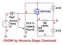
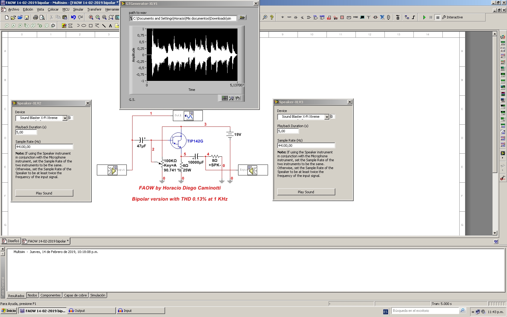
This is what I came up with, with what I have lying around. Output cap is 1000uF, positive towards the circuit, negative to speaker (+). Hope I got that right. MOSFET is IRFZ44N. Input cap is 47uF/25V. Thanks for the design, inspiration, and wealth of information.
I have read that output cap is a high pass function in relation to speaker impedance. If I use 8 Ohm speakers, 1000uF is theoritically flat to ~200Hz and -3dB at 20Hz. Is that correct? If so, I am thinking of increasing the value of output capacitor. Thank you very much.
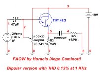
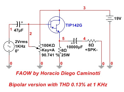
This circuit has some advantages over the circuit that opens this same thread.
The advantages offered by this circuit may not be easily visualized under simulation software, since they are mainly due to the reduction of the static voltage to which two elements of the input circuit are now exposed. It is a known fact that every element exposed to a lower static voltage, shows lower levels of distortion (mainly at low frequency). The difference could be marginal and inaudible, although that could be measured to know in particular if that is the case in this circuit.
There is another advantage that would be a marginal reduction in thermal noise.
The 10 uF capacitor is now exposed to around 4 Vdc of static voltage (assuming 0 Vdc in the output of the previous stage), when it was originally close to 15.67 Vdc. That marks a reduction of 3.92 times in the static voltage. We know that the distortion also manifests differently according to the static voltage between the capacitor plates.
The resistors arranged in series connection (see the 10K value and the 47K value) were exposed between the extremes at 19Vdc. Now, the ends of the 100K trimpot are exposed to only 9.5 Vdc, so the dissipation is much lower and, in some way also, the thermal noise.
Regards
Attachments
Last edited:
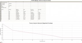
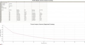
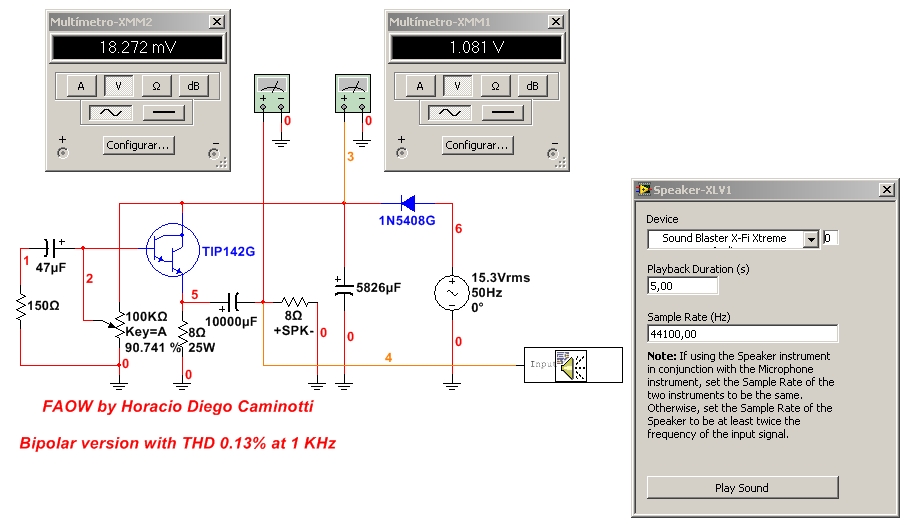
0,483 W RMS at 8 ohms and THD 0,13 % at 1 KHz (0,966 Wp) 😉
0,945 W RMS at 4 ohms and THD 0,48 % at 1 KHz (1,890 Wp) 🙄
Like headphones buffer:
0,122 W RMS at 32 ohms and THD 0,047 % at 1 KHz (0,245 Wp). Output cap of 3300 uF only.
Attachments
Last edited:
0,483 W RMS at 8 ohms and THD 0,13 % at 1 KHz (0,966 Wp) 😉
0,945 W RMS at 4 ohms and THD 0,48 % at 1 KHz (1,890 Wp) 🙄
Like headphones buffer:
0,122 W RMS at 32 ohms and THD 0,047 % at 1 KHz (0,245 Wp). Output cap of 3300 uF only.
Attachments
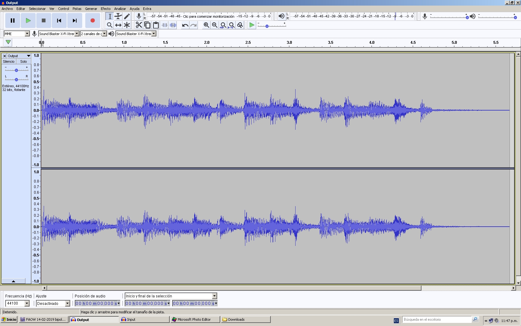
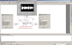
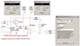
Next, with the help of LabVIEW tools within the simulation environment of the Multisim 14, I carry out a virtual test to compare the sound that is injected into the input, with that obtained at the output of the bipolar buffer.
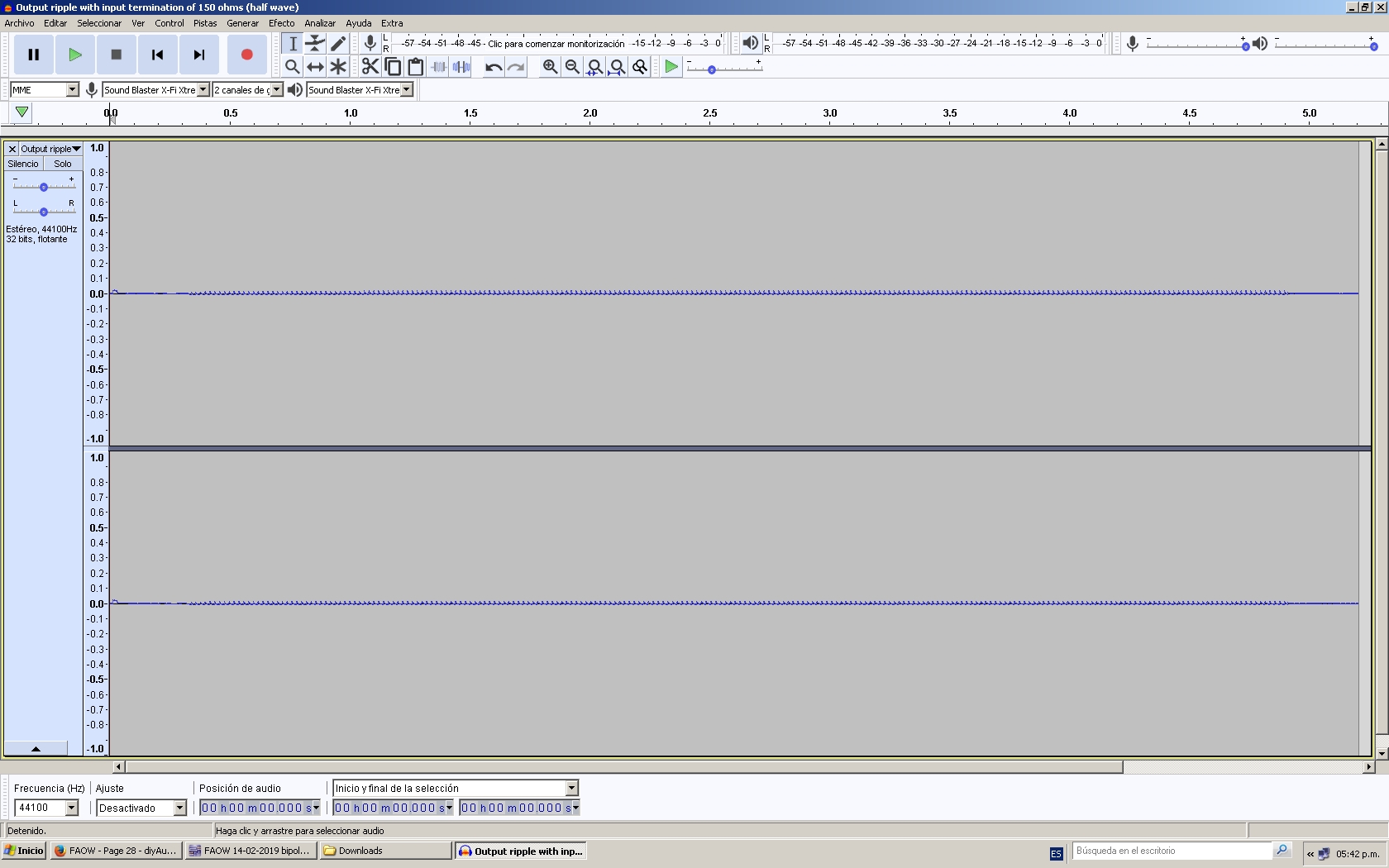
As you can hear, under resistive load of 8 ohms, it is not possible to find appreciable differences.
Sampling was 44100 Hz. The duration of the .wav files is approx. 5 seconds.
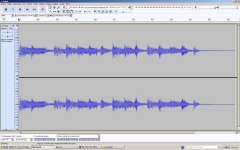
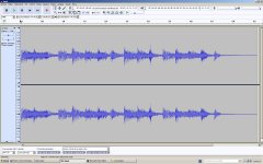
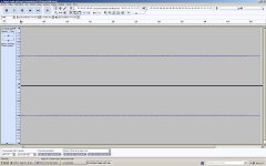
I upload additional images of the captures of the two waveforms with Audacity (Input and Output).
The sound files are in .wav format, so you should change the termination of the .asc files by .wav, in order to reproduce them and make the comparison in your sound equipment.
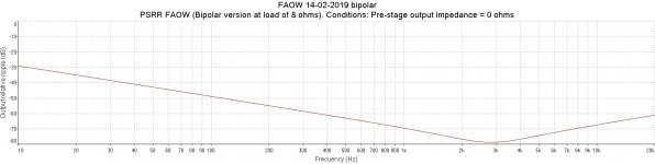
In the same way, a PSRR test could be carried out with real values of filtering in the power supply, to hear how intrusive the ripple of the power supply line would be in the output of the buffer.
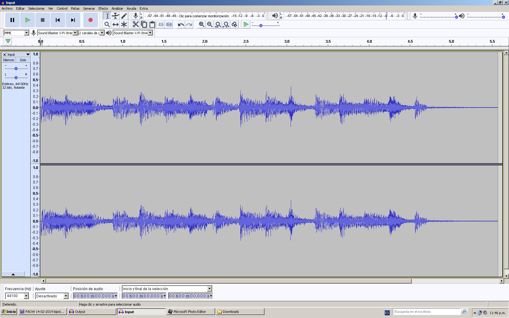
As you can hear, under resistive load of 8 ohms, it is not possible to find appreciable differences.
Sampling was 44100 Hz. The duration of the .wav files is approx. 5 seconds.
I upload additional images of the captures of the two waveforms with Audacity (Input and Output).
The sound files are in .wav format, so you should change the termination of the .asc files by .wav, in order to reproduce them and make the comparison in your sound equipment.
In the same way, a PSRR test could be carried out with real values of filtering in the power supply, to hear how intrusive the ripple of the power supply line would be in the output of the buffer.
Attachments
Last edited:
With input termination of 150 ohms (Zout of a conventional opamp, for example), the PSRR is around of 35,88 dB at 100 Hz. Remember to change termination .asc by .wav.
Then, with a filter capacitor of only 4700 uF (somewhat mediocre for the typical consumption of this buffer), the maximum signal-to-noise ratio would be around 45,98 dB.
Attachments
Last edited:
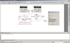
This is just out of curiosity. What would happen if we feed the same circuit from a half-wave rectification, maintaining a similar average voltage value of the power supply?
Would the background noise due to the ripple be more or less intrusive in the audible spectrum, compared to its full-wave counterpart?
In the example, it has been compensated with the value of the main filtering, to maintain the 19 Vdc.
Would the background noise due to the ripple be more or less intrusive in the audible spectrum, compared to its full-wave counterpart?
In the example, it has been compensated with the value of the main filtering, to maintain the 19 Vdc.
Attachments
I plan on building the FAOW variation #2 since I have the parts here. I have some Noguchi finemet-core transformers that I have been drying to try. Since tubes have been on the back-burner, this should be a great excuse to press them into service.
The only question I have is if the IXTH20N50D would work? I have a matched pair that someone sent me long ago. I assume these are just capable of more current, but are otherwise similar? Since we're going for the other end of the current spectrum, I wasn't sure if running this device at such low current would be an issue.
The only question I have is if the IXTH20N50D would work? I have a matched pair that someone sent me long ago. I assume these are just capable of more current, but are otherwise similar? Since we're going for the other end of the current spectrum, I wasn't sure if running this device at such low current would be an issue.
I think you should try them. They worked pretty well for the
DeLite: http://www.firstwatt.com/pdf/art_delite.pdf
DeLite: http://www.firstwatt.com/pdf/art_delite.pdf
Thanks! I think that is what they were for. I had ordered a few sets of matched devices for an F5 many years ago and the seller included a matched pair of these (probably for the DeLite). I'll read through the PDF again and give it a go!
The only problem is that I'm flying blind with no test equipment. I fried the audio in/out pins in my Mac attempting some tests using software a few months ago (I swapped the in and out...oops). Hopefully it just sounds good and I'm blissfully ignorant of what's actually going on 😀
The only problem is that I'm flying blind with no test equipment. I fried the audio in/out pins in my Mac attempting some tests using software a few months ago (I swapped the in and out...oops). Hopefully it just sounds good and I'm blissfully ignorant of what's actually going on 😀
Perhaps such a simple amp will get by with a voltmeter and some ears....

- Home
- Amplifiers
- Pass Labs
- FAOW